Two-way DC-DC converter

a converter and two-way technology, applied in the direction of electric variable regulation, process and machine control, instruments, etc., can solve the problems of large switching loss and insufficient performance, and achieve the effect of reducing switching loss, simple configuration and improving conversion efficiency

Active Publication Date: 2007-02-13
HONDA MOTOR CO LTD
View PDF5 Cites 34 Cited by
  • Summary
  • Abstract
  • Description
  • Claims
  • Application Information

AI Technical Summary

Benefits of technology

[0014]According to a first aspect of the present invention, a wave form of a current by switching can be changed into a sinusoidal one by an LC resonant circuit. Thereby, OFF timing of a switching element can be set in the vicinity of a zero crossing point of a current value. Accordingly, switching in the vicinity of the zero crossing point of the current value can be realized to cause remarkable reduction of switching losses.
[0015]Furthermore, a control system with a simple configuration can be realized because a primary DC-AC transformation section and a secondary DC-AC transformation section can be controlled by the same drive signal. At this time, a conversion efficiency can be improved, because a larger dead time of switching elements, which prevents shortings of switchi

Problems solved by technology

However, there has been a problem that the configuration in which a DC step-up circuit and a DC step-down circuit are disposed in parallel with each other between two DC power supply systems has a large scale circuit, and, at simultaneous operation, enough performance cannot be obtained due to, for example, voltage losses in the circuit.
Moreover, in the two-way DC-DC converter as disclose

Method used


Image

  • Two-way DC-DC converter
  • Two-way DC-DC converter
  • Two-way DC-DC converter

Examples


Embodiment Construction

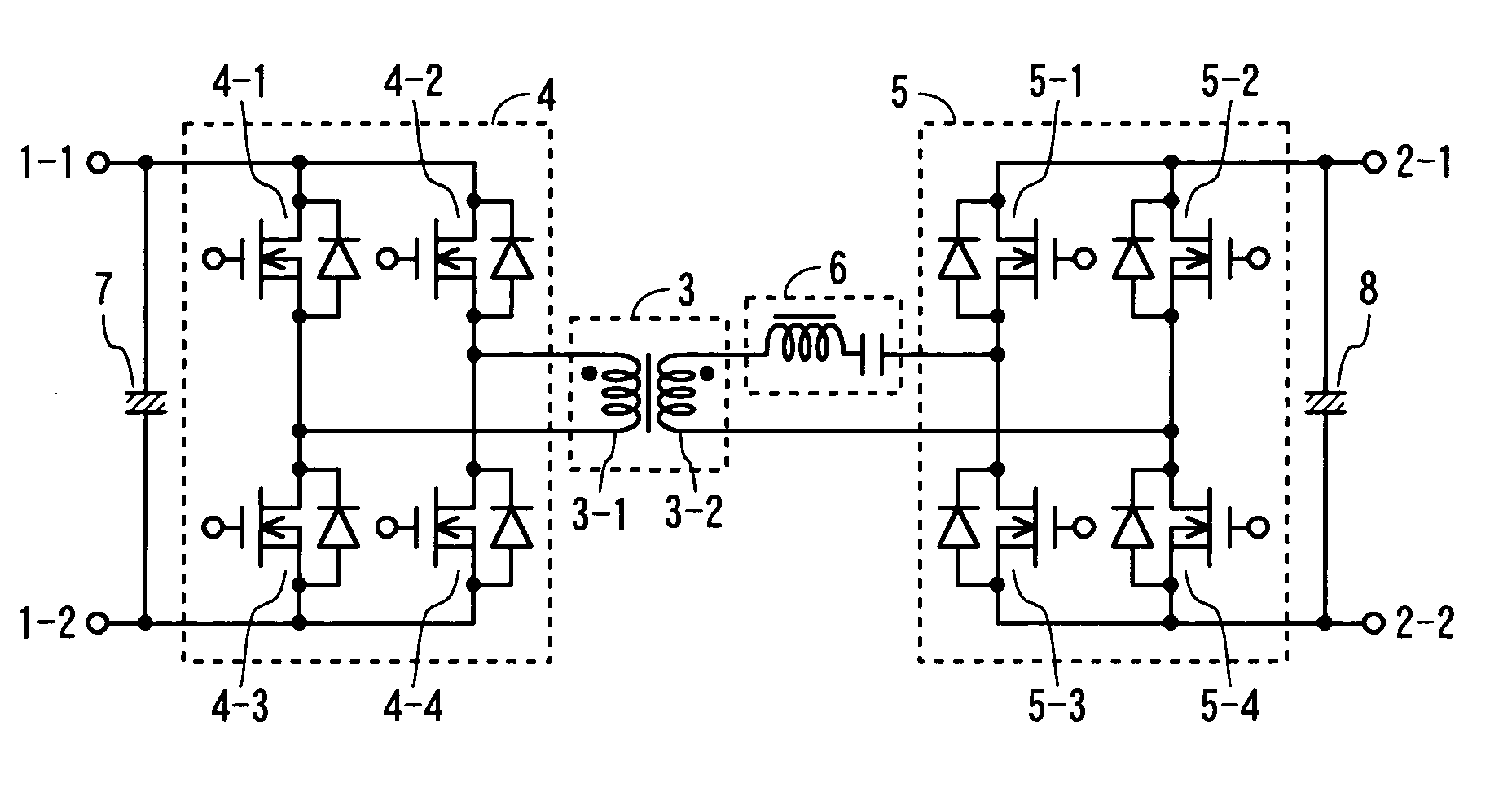
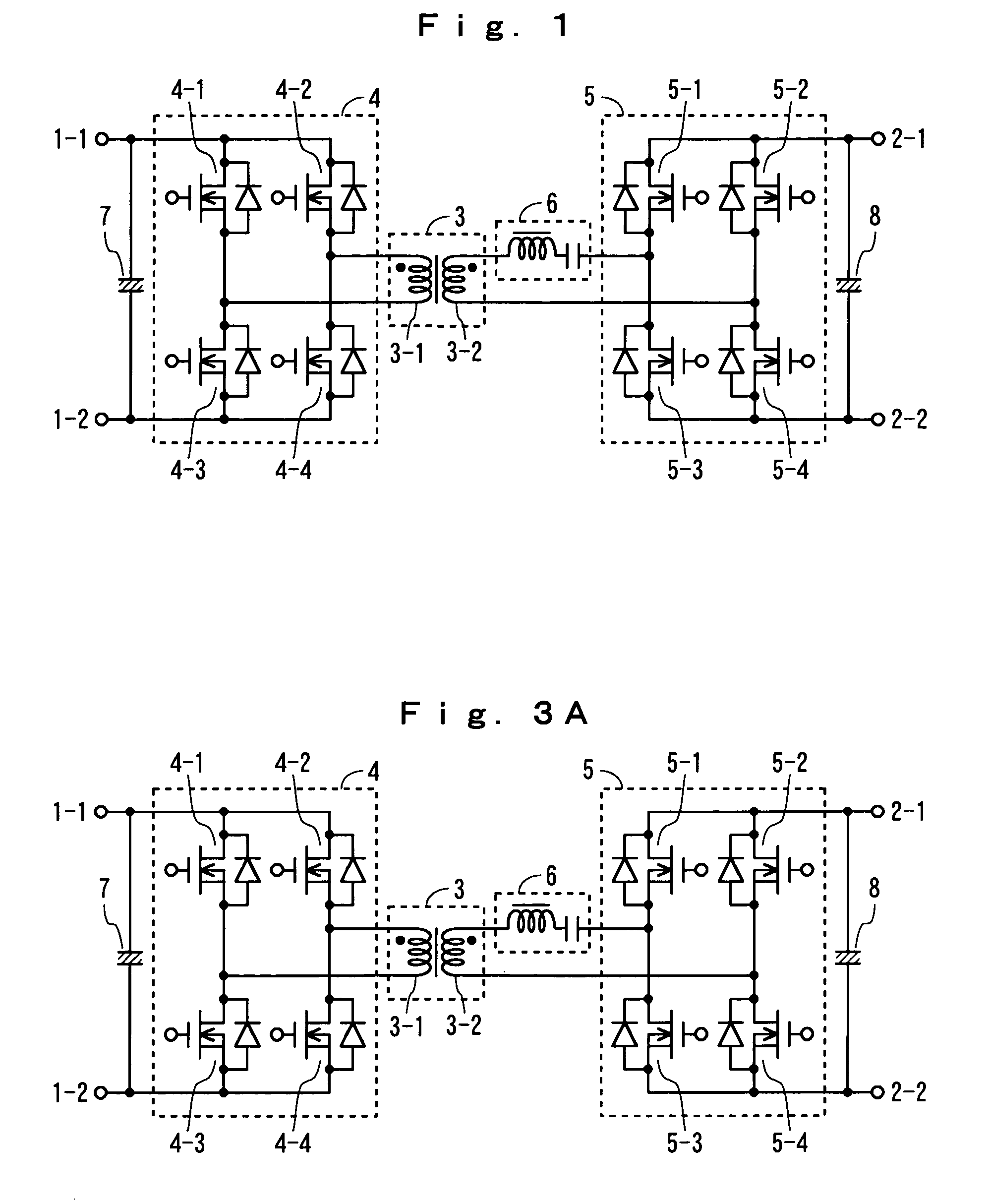
[0022]Hereinafter, the present invention will be explained in detail, referring to drawings. FIG. 1 is a circuit diagram showing one embodiment of a two-way DC-DC converter according to the present invention. The two-way DC-DC converter according to the present embodiment realizes two-way exchange of electric power between a DC power supply connected to terminals 1-1, 1-2 for a low-voltage side and terminals 2-1, 2-2 for a high-voltage side through a transformer 3. Hereinafter, the side of the terminals 1-1, 1-2 for a low-voltage side and that of the terminals 2-1, 2-2 for a high-voltage side will be sometimes called as a primary side, and a secondary side, respectively.

[0023]The transformer 3 comprises a winding wire 3-1 for a low-voltage side and a winding wire 3-2 for a high-voltage side. A step-up voltage ratio of the two-way DC-DC converter is defined by a turns ratio between the winding wire 3-1 for the low-voltage side and the winding wire 3-2 for the high-voltage side. A swi...


PUM


Abstract

Rectifying elements are connected in parallel with switching elements 4-1 through 4-4 in a switching section 4 for the lower voltage side and rectifying elements are connected in parallel with switching elements 5-1 through 5-4 in a switching section 5 for the higher voltage side. An LC resonant circuit 6 is provided between the winding wire 3-2 for the high-voltage side in the transformer 3 and the switching section 5 for the higher voltage side; currents which flows on the primary side and the secondary side is changed into a sinusoidal one; and switching is executed in the vicinity of the zero crossing points of the currents.

Description

BACKGROUND OF THE INVENTION[0001]1. Field of the Invention[0002]The present invention relates to a two-way DC-DC converter, and more particularly, to a two-way DC-DC converter which can reduce switching losses and is able to simplify the control system.[0003]2. Description of the Related Art[0004]For example, some of vehicles have two power supply systems with different voltages. When two-way exchange of electric power in such two direct-current (DC) power supply systems with different voltages is executed, it is common to adopt a configuration, in which a DC step-up circuit and a DC step-down circuit are disposed in parallel with each other between the DC power supply systems and the circuits are used, as necessary.[0005]Moreover, there has been made a proposal in which, when two-way exchange of electric power between the DC power supply systems is executed, a two-way DC-DC converter is used in order to obtain an enough high DC voltage by a small-scale circuit.[0006]For example, th...

Claims


Application Information

Patent Timeline
IPC IPC(8): H02M3/335H02M7/5387H02M3/28H02M3/135H02M3/337
CPCH02M3/33592H02M3/337Y02B70/1491Y02B70/1433Y02B70/1475H02M2001/0048Y02B70/10H02M1/0048H02M3/33573H02M3/01A45C11/00A45C2011/002
Inventor EGUCHI, HIROYUKISHIMIZU, MOTOHIRO
Owner HONDA MOTOR CO LTD
Why Eureka
Try Eureka