Imaging inspection apparatus

a technology of inspection apparatus and inspection chamber, which is applied in the direction of liquid/fluent solid measurement, machines/engines, instruments, etc., can solve the problems of reducing the accuracy of inspection equipment, limiting the system, and reducing the length of inspection equipment, so as to enhance the shipping of the equipment and reduce the length

Active Publication Date: 2007-02-13
SURESCAN CORP
View PDF24 Cites 73 Cited by
  • Summary
  • Abstract
  • Description
  • Claims
  • Application Information

AI Technical Summary

Benefits of technology

[0022]It is another object of the invention to provide an imaging inspection apparatus which enables facile inspection of articles moving along a conveyor with articles substantially not being subjected to undesirable vibrations and / or other forces.
[0023]It is yet another object of the invention to provide such an imaging inspection apparatus which can be reduced in length from its normal operating orientation, e.g., to enhance shipping of the apparatus.

Problems solved by technology

However, practical limitations of pixel size and resolution tend to limit this system to inspection of items with small fields of view.
The accurate, rapid inspection of moving articles such as multiple luggage pieces, often having many different sizes and shapes, is, understandably, a relatively difficult task, as indicated by just some of the difficulties mentioned in some of the above patents and elsewhere in the literature pertaining to this art with respect to articles in both stationary and moving positions.
Undesirable movement of such articles along the path on which these travel may result in erroneous readings.
In large apparatus in which a conveyor is the best means of such article transport, undesirable vibrations or other motion by the parts of the conveyor (e.g., the rollers, belts, drive motor) may contribute to such errors.

Method used


Image

  • Imaging inspection apparatus
  • Imaging inspection apparatus
  • Imaging inspection apparatus

Examples


Embodiment Construction

[0029]For a better understanding of the present invention, together with other and further objects, advantages and capabilities thereof, reference is made to the following disclosure and appended claims in connection with the above-described drawings. Like figure numbers will be used from FIG. to FIG. to identify like elements in these drawings.

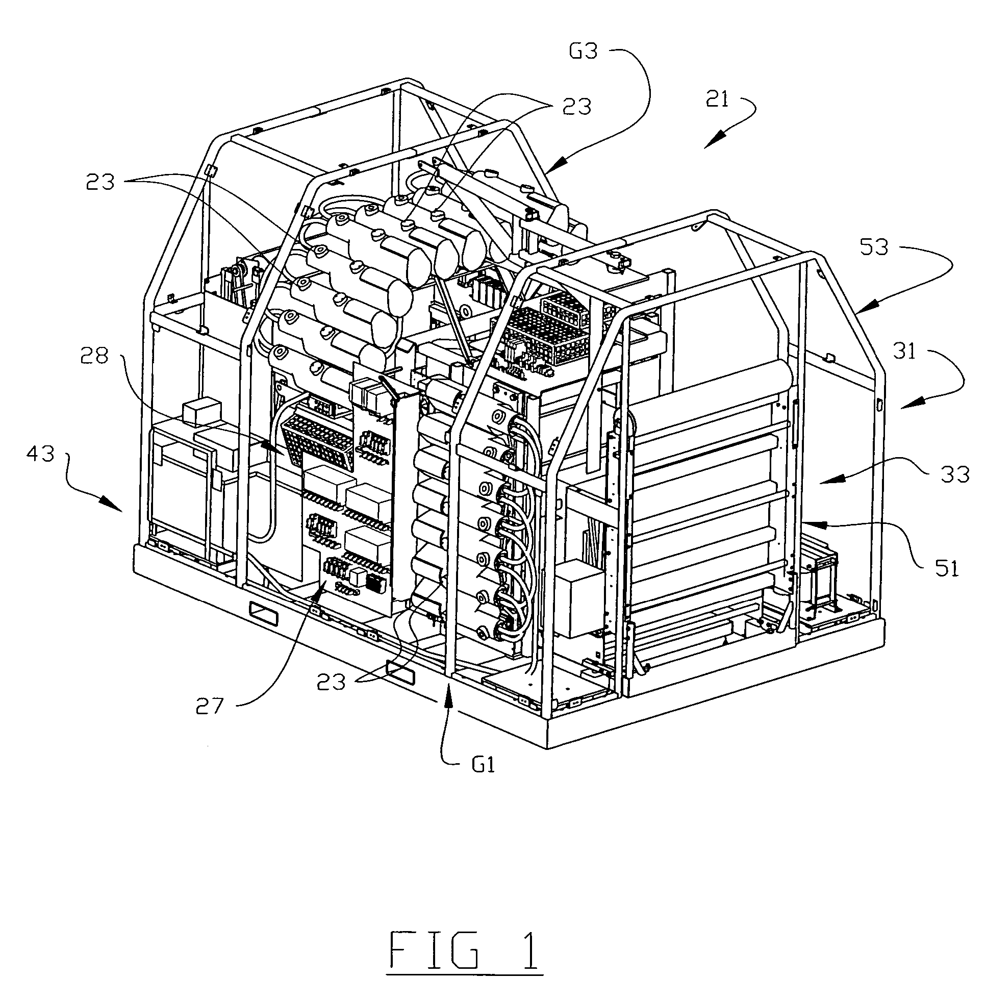
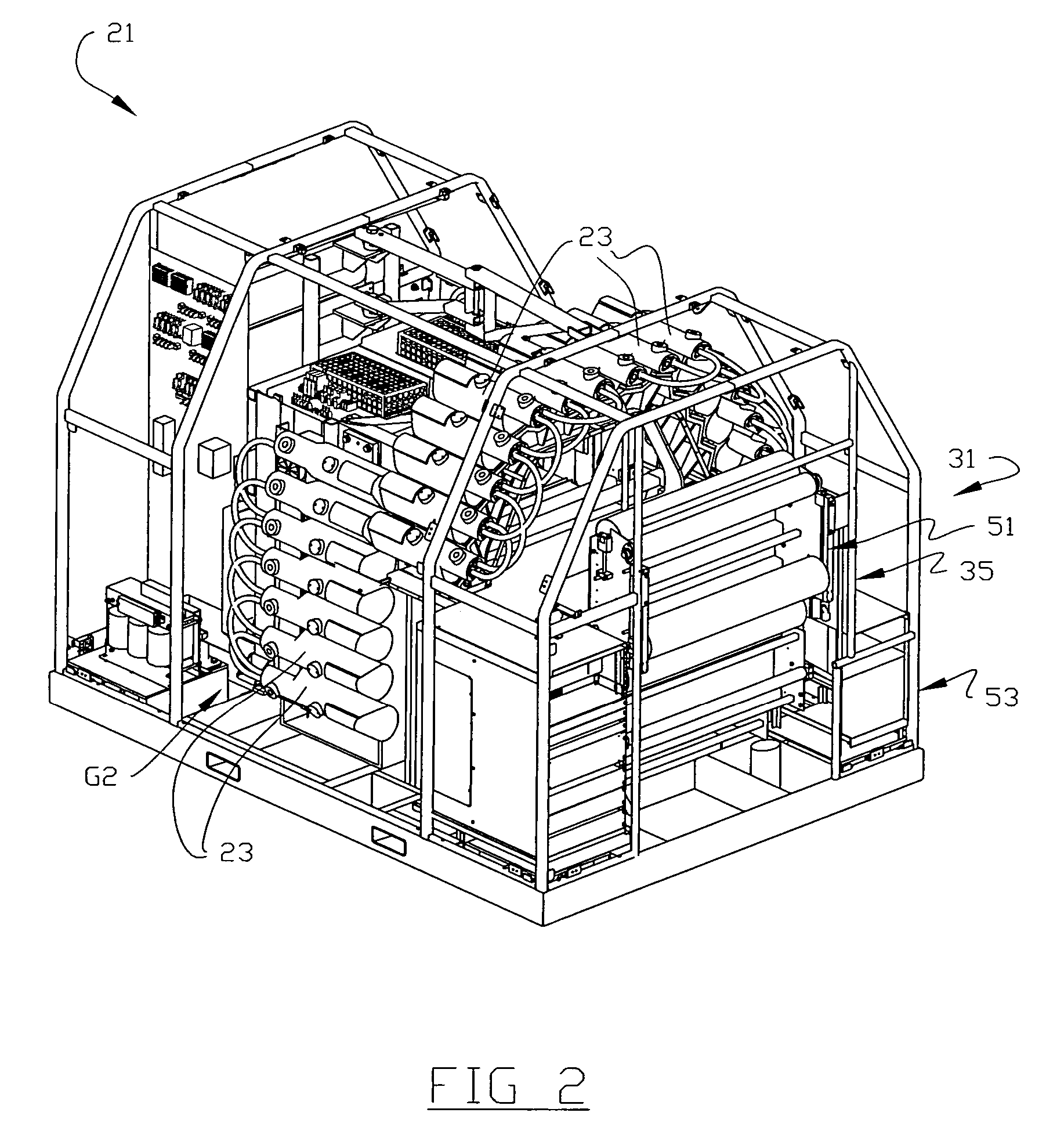
[0030]In FIGS. 1 and 2, there is illustrated an imaging inspection apparatus 21 according to one embodiment of the invention. As indicated, apparatus 21 is particularly designed for inspecting (and detecting) objects (not shown) which might be located within closed articles such as personal luggage of an airplane traveler. As such, the apparatus is ideally designed for placement and use within an airport or other transportation facility in which large numbers of such articles are received and transported. Apparatus 21 is adapted for inspecting and detecting concealed objects such as explosives, weapons, etc., including in solid and powder for...


PUM

PropertyMeasurementUnit
thicknessaaaaaaaaaa
diameteraaaaaaaaaa
widthaaaaaaaaaa

Abstract

An imaging inspection apparatus which utilizes a plurality of individual imaging inspection devices (e.g., X-ray Computer Tomography scanning devices) positioned on a frame for directing beams onto articles having objects therein to detect the objects based on established criteria. The apparatus utilizes a conveyor which is not physically coupled to the frame having the imaging inspection devices to pass the articles along a path of travel to an inspection location within the apparatus, whereupon the inspection devices direct beams onto the article and the beams are detected and output signals provided to a processing and analysis assembly which analyzes the signals and identifies certain objects which meet the criteria.

Description

TECHNICAL FIELD[0001]The invention relates to inspection apparatus designed for inspecting articles such as luggage, baggage, mail, etc. More particularly, the invention relates to such apparatus which utilize X-ray imaging and the like.BACKGROUND OF THE INVENTION[0002]The use of imaging inspection apparatus is known, including those which utilize X-ray imaging. Such apparatus are used to inspect articles such as personal luggage of airplane travelers at airports for such undesirable items as explosives and drugs.[0003]One particularly successful example of such apparatus is that which utilizes what is referred to in the art as “X-ray Computer Tomography” (hereinafter also referred to as, simply, XCT). XCT apparatus are in wide use in the medical field for providing medical imaging such as patient body X-rays. XCT (often referred to in the medical profession simply as “CT scanning”) produces a cross sectional image from a grouping of attenuation measurements taken at different angle...

Claims


Application Information

Patent Timeline
Patent Type & Authority Patents(United States)
IPC IPC(8): G01N23/04
CPCB65G21/14G01V5/0008G01N23/046G01N2223/419
Inventor CHAPIN, FLETCHER L.KOZOL, JOHN E.
Owner SURESCAN CORP
Why Eureka
Try Eureka