
Microcomputer minimizing influence of bus contention

a microcomputer and bus contention technology, applied in the field of microcomputers, can solve the problems of dma start cycle disturbance, limited access, bottleneck in fast operation, etc., and achieve the effect of reducing the influence of bus contention and flexibly changing setup-time/hold-tim

Inactive Publication Date: 2007-02-13
RENESAS ELECTRONICS CORP
View PDF18 Cites 2 Cited by
  • Summary
  • Abstract
  • Description
  • Claims
  • Application Information

AI Technical Summary

Benefits of technology

[0013]An object of the invention is to provide a microcomputer, which can minimize an influence of bus contention between a CPU and a DMA, and can flexibly change setup-time / hold-time.
[0015]According to the invention, an influence of bus contention between a CPU and a DMA can be minimized, and setup-time / hold-time can be flexibly changed so that fast external interference can be achieved.

Problems solved by technology

The following problem occurs when parallel data, which are input in synchronization with an external signal, are taken in by the DMA.
First, a DMA start cycle may be disturbed due to bus contention between a CPU and the DMA.
Since this causes a bottleneck in a fast operation when taking in external data, it is necessary to impose access limitation on the CPU.
This also causes a bottleneck in the fast operation.

Method used


Image

  • Microcomputer minimizing influence of bus contention
  • Microcomputer minimizing influence of bus contention
  • Microcomputer minimizing influence of bus contention

Examples


Embodiment Construction

[0040]Embodiments of the invention will now be described with reference to the drawings. In the figures, the same or corresponding portions bear the same reference numbers, and description thereof is not repeated.

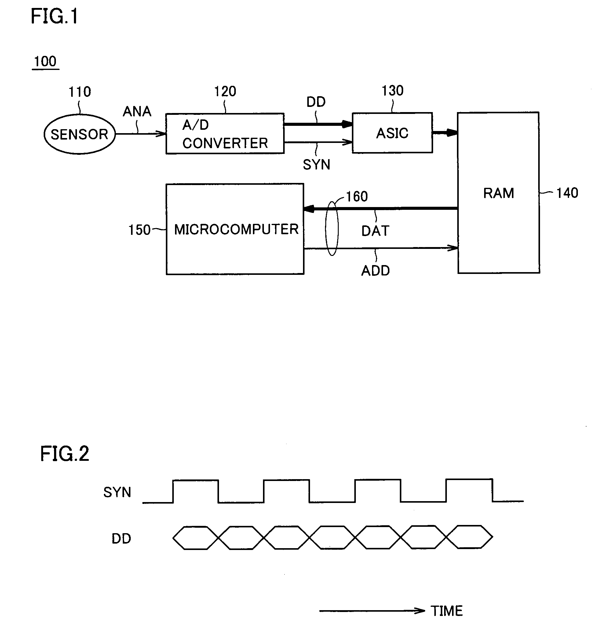
[0041]FIG. 1 is a block diagram showing a block structure of a microcomputer system 100 forming a background of an embodiment of the invention.

[0042]Referring to FIG. 1, microcomputer system 100 includes a sensor 110, an A / D converter 120, an ASIC (Application Specific Integrated Circuit) 130, a RAM 140, a microcomputer 150 and an external bus 160.

[0043]Sensor 110 detects a certain event, and provides an analog signal ANA corresponding to it. A / D converter 120 converts analog signal ANA to digital data DD, and provides a synchronous signal SYN. In this embodiment, it is assumed that the A / D conversion (an output data width of digital data DD) has a precision of 8 bits, for the sake of convenience.

[0044]ASIC 130 receives digital data DD and synchronous signal SYN, and detect...


PUM


Abstract

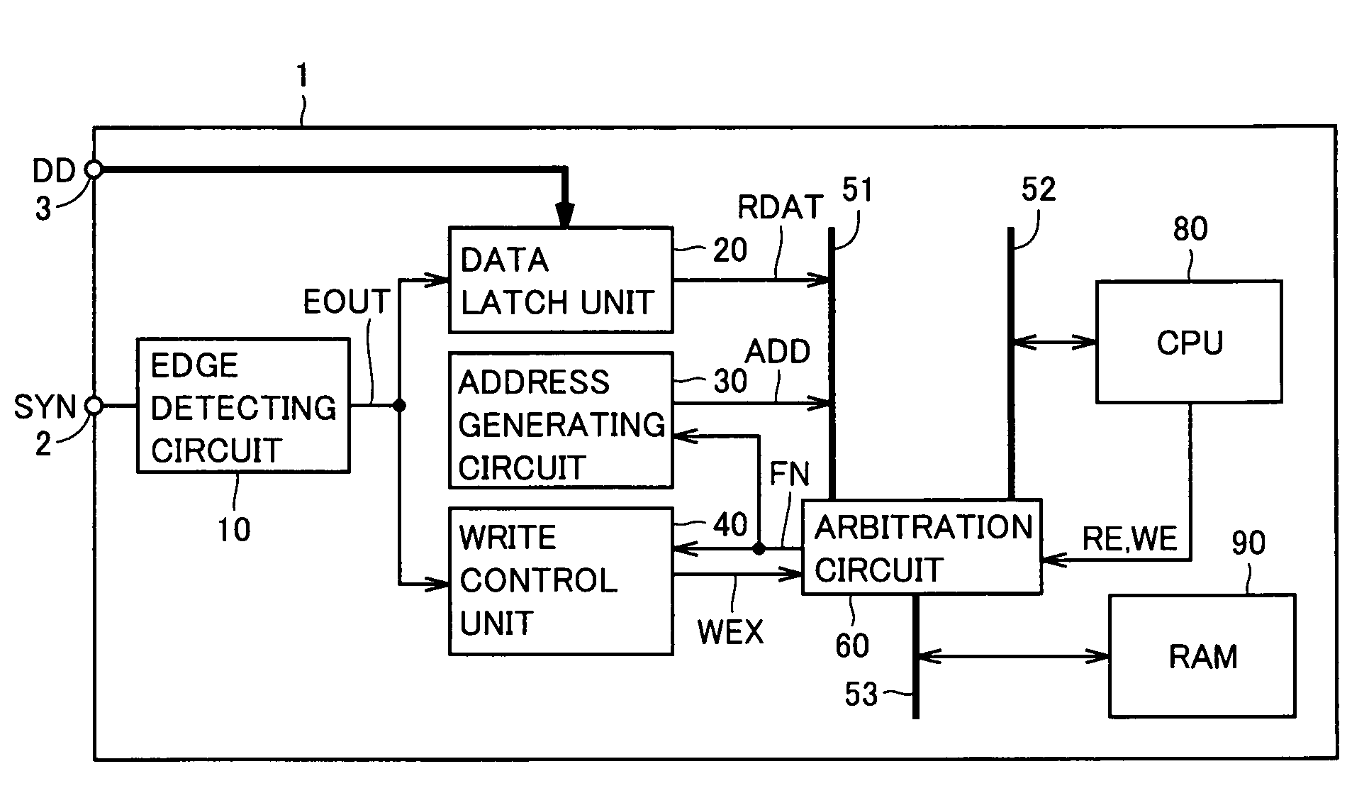
An edge detecting circuit detects an input level change (edge) of a synchronous signal provided from a synchronous signal input terminal. A data latch unit latches digital data provided from an external data input terminal. An address generating circuit provides an address signal. A write control unit activates / deactivates a write enable signal for writing to a RAM. An arbitration circuit monitors a write control enable signal, a read enable signal and a write enable signal, and detects a cycle, in which a CPU does not access the RAM.

Description

BACKGROUND OF THE INVENTION[0001]1. Field of the Invention[0002]The present invention relates to a microcomputer, and particularly to a microcomputer taking data, which is transmitted in synchronization with a certain signal, into its internal storage device.[0003]2. Description of the Background Art[0004]For example, the following conventional techniques have been used for taking multiple bits of data, which are transmitted in synchronization with a certain signal, into a storage device such as an internal RAM (Random Access Memory) of a microcomputer.[0005]A conventional interface circuit can hold a write control signal, an address control signal and data at rising and falling of a clock signal, and can reduce waiting times required for reading and writing (see, e.g., Japanese Patent Laying-Open No. 2003-067324).[0006]A conventional microcomputer system can control external transfer of data to and from the microcomputer, and can also perform internal arithmetic processing of the m...

Claims


Application Information

Patent Timeline
Patent Type & Authority Patents(United States)
IPC IPC(8): G06F13/38G06F13/28G06F12/00G06F13/00G06F13/18G06F15/78
CPCG06F12/00G06F13/00G06F15/78G06F13/28G06F13/18
Inventor SHINGAKI, YASUNORI
Owner RENESAS ELECTRONICS CORP
Learn More