Cylinder rod with position sensor surface markings

a technology of position sensor and cylinder rod, which is applied in the field of surface markings, can solve the problems of preventing accurate affecting the accuracy of the determination of the position of the rod, and fading of surface markings on any material

Inactive Publication Date: 2007-02-20
CATERPILLAR INC
View PDF24 Cites 26 Cited by
  • Summary
  • Abstract
  • Description
  • Claims
  • Application Information

AI Technical Summary

Problems solved by technology

Over time, surface markings on any material may wear or fade due to friction, heat, and / or corrosion.
Further, a certain degree of wear may make the surface markings unrecognizable to a sensor, thereby preventing accurate determination of the rod position.
The surface marking produced by the method of the '916 patent may not withstand repeated exposure to friction and wear produced on a hydraulic cylinder rod.
Further, the chromium-plated surface of the metal bar may cause more wear on cylinder-head seals as compared to other materials.
In addition, operation of the marking laser may be expensive and time consuming.

Method used


Image

  • Cylinder rod with position sensor surface markings
  • Cylinder rod with position sensor surface markings
  • Cylinder rod with position sensor surface markings

Examples


Embodiment Construction

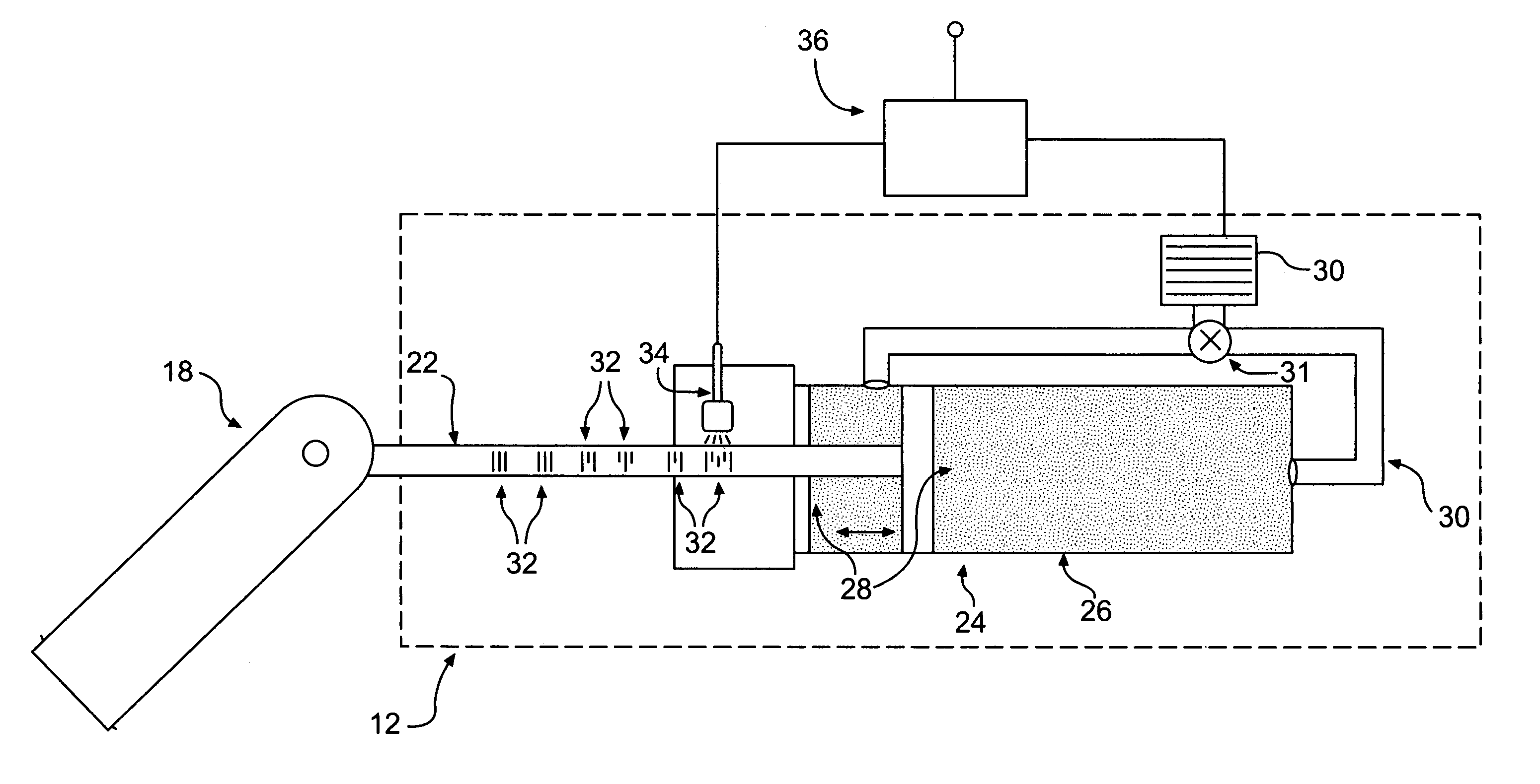
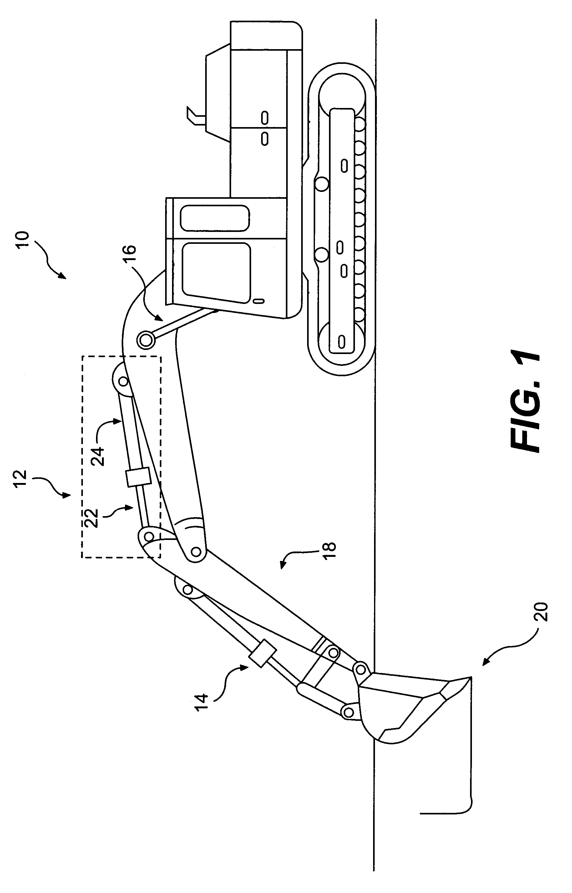
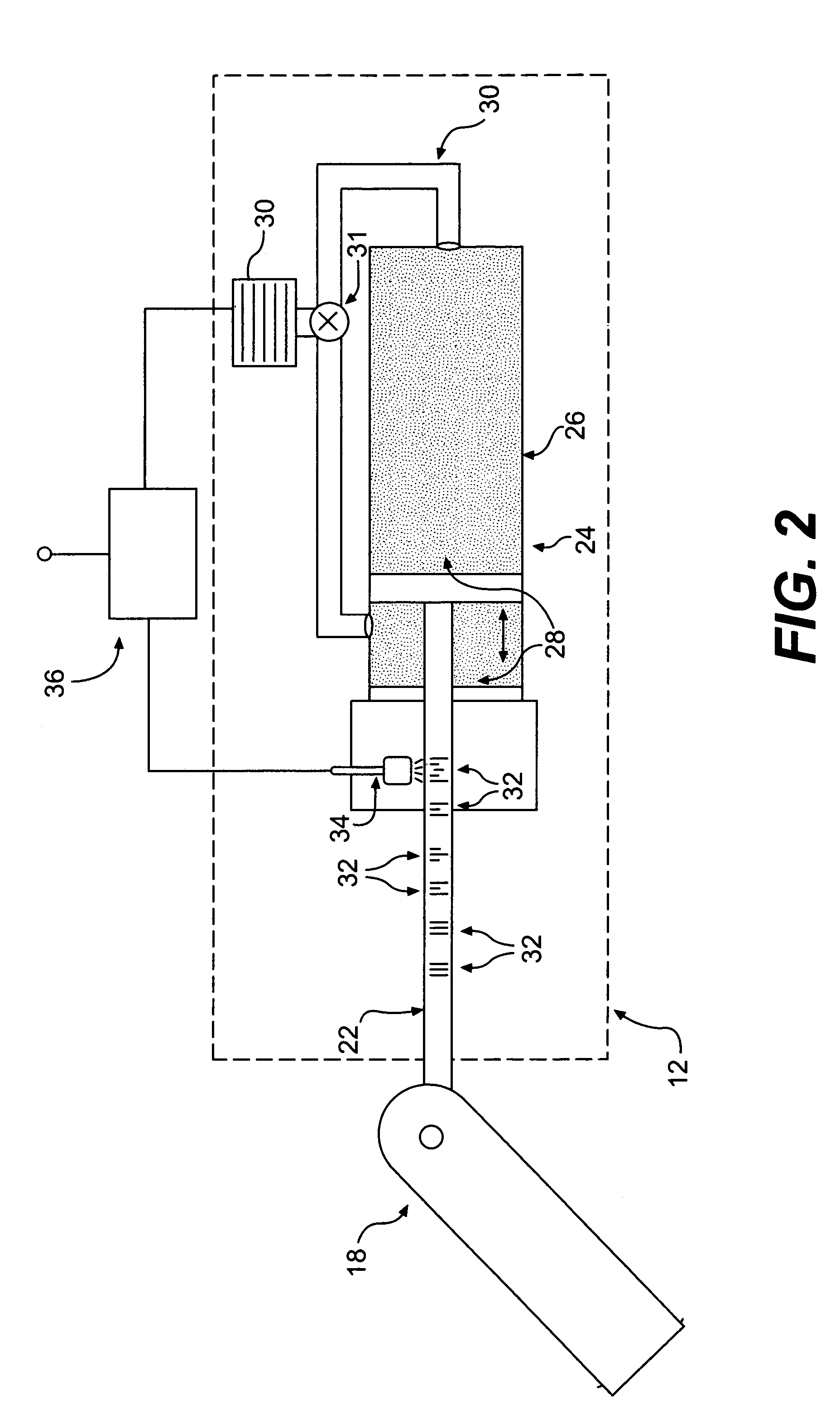
[0014]FIG. 1 illustrates a work machine 10 of the present disclosure. While work machine 10 is shown as an excavator, work machine 10 may include any type of work machine that includes one or more hydraulic systems. Such work machines may include, for example, track-type tractors, dump trucks, skid steers, aircraft, boats, cranes, etc. As illustrated, work machine 10 may include several hydraulic cylinder systems 12, 14, 16, which may control the movement of an excavator arm 18 and / or a bucket 20.

[0015]Hydraulic cylinder systems 12, 14, 16 may include a cylinder rod 22 and cylinder 24. During operation, cylinder rod 22 may slide longitudinally within a chamber (as shown in FIG. 2) of cylinder 24. Cylinder rod 22 and / or cylinder 24 may be mechanically coupled to one or more components of work machine 10, including excavator arm 18. The movement of cylinder rod 22 within cylinder 24 may provide power to and control the movement of one or more components of work machine 10.

[0016]FIG. 2...


PUM

PropertyMeasurementUnit
weight percentaaaaaaaaaa
thicknessaaaaaaaaaa

Abstract

A cylinder rod with wear-resistant surface markings is provided. The cylinder rod may include a rod substrate, a thermal-spray coating disposed on a surface of the substrate, and one or more surface markings disposed on the coating at predetermined locations along the length of the cylinder rod.

Description

TECHNICAL FIELD[0001]This disclosure pertains generally to surface markings and, more particularly, to surface markings formed on a thermal-spray coating of a hydraulic cylinder rod.BACKGROUND[0002]Many construction and earth moving machines use hydraulic or pneumatic cylinders to move work tools such as buckets on backhoes, loaders, and excavators. The cylinders may include a cylinder chamber at least partially filled with hydraulic fluid. A cylinder rod may be configured to slide along an axis of the cylinder chamber, and hydraulic fluid may be introduced into the chamber or removed from the chamber to extend or retract the rod. Often, the rod position must be known so that movement of the work tool can be monitored and controlled.[0003]Cylinder rod surface markings, such as bar codes, may help to determine the position of the rod. The surface markings may be positioned at predetermined intervals along the cylinder rod, and each marking may correspond to a different location on th...

Claims


Application Information

Patent Timeline
Patent Type & Authority Patents(United States)
IPC IPC(8): F01B25/26B23K26/00
CPCF16J7/00F15B15/2807B41M5/24B41M5/262F15B15/2846
Inventor KUCHER, TRENT STEVENRAAB, KAREN RENEEJIANG, XIANGYANG
Owner CATERPILLAR INC
Why Eureka
Try Eureka