Hydraulic controlled fan clutch with integral cooling

a fan clutch and hydraulic control technology, applied in mechanical actuated clutches, mechanical equipment, mechanical actuation clutches, etc., can solve the problems of inability to cycle repeat in short durations of time, low thermal capacity of dry friction clutch assemblies, and inability so as to reduce improve the cooling capacity. , the effect of reducing the size of the drive system

Inactive Publication Date: 2007-02-20
BORGWARNER INC
View PDF20 Cites 42 Cited by
  • Summary
  • Abstract
  • Description
  • Claims
  • Application Information

AI Technical Summary

Benefits of technology

[0013]Another advantage of the present invention is that it includes multiple cooling devices for additional cooling of the fan drive system. The cooling devices include a variable cooling circuit and a dual part clutch housing with integrated cooling fins. In having increased fan drive system cooling the present invention is capable of rotating at high speeds for increased cooling capability and minimizes size of the drive system.
[0014]Furthermore, the present invention provides a fan drive system that incorporates cooling, engagement circuitry, and control circuitry within a single assembly allowing for ease of assembly and integration into a larger system such as an engine or a vehicle, while at the same time being capable of utilizing external control circuitry.
[0015]Moreover, the present invention defaults to an engaged state providing engine cooling when control systems are inoperative and in so doing also provides diagnostic ease.
[0016]Yet another advantage of the present invention is that it provides versatility in control in that multiple style control circuits may be utilized depending upon the application.

Problems solved by technology

The dry friction clutch assemblies generally have low thermal capacity, since they typically do not incorporate fluid flow cooling mechanisms.
Thus, the clutch assemblies have minimal cooling capability and are unable to cycle repeat in short durations of time.
Also, because of low thermal capacity, the clutch assemblies are also limited in torsional capacity, such that they are incapable of engaging at high engine revolutions per minute (rpm) or high engine speeds.
The thermal energy that is generated during engagement at high engine rpm speeds can “burn up” or cause the clutch assembly to become inoperative.
Viscous drives are never fully engaged for internal viscous shear purposes.
Unfortunately, viscous drives are also thermally and torsionally limited.
Viscous drives are always slipping to some degree causing them to be incapable of turning at fully engaged peak operating speeds or at higher speeds than originally designed.
Viscous drives are further limited in that the more engine cooling needed the larger and more costly the viscous drive and cooling fan that is required.
Thus, for increased engine cooling requirements viscous drives can become impractical in size and cost.

Method used


Image

  • Hydraulic controlled fan clutch with integral cooling
  • Hydraulic controlled fan clutch with integral cooling
  • Hydraulic controlled fan clutch with integral cooling

Examples


Embodiment Construction

[0025]In the following figures the same reference numerals will be used to refer to the same components. While the present invention is described with respect to a method and system for a hydraulically controlled fan drive system, the present invention may be adapted and applied to various systems including: vehicle systems, cooling systems, fan drive systems, friction drive systems, or other systems.

[0026]In the following description, various operating parameters and components are described for one constructed embodiment. These specific parameters and components are included as examples and are not meant to be limiting.

[0027]Also, in the following description various fan drive components and assemblies are described as an illustrative example. The fan drive components and assemblies may be modified depending upon the application.

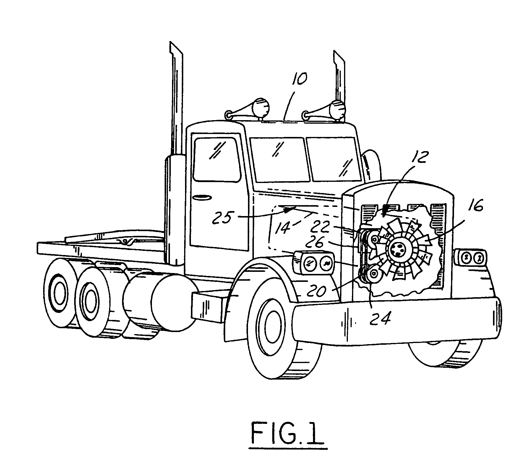
[0028]Referring now to FIG. 1, a perspective view of a vehicle 10 utilizing a hydraulically controlled fan drive system 12 in accordance with an embodimen...


PUM


Abstract

A hydraulically controlled fan drive system (12) having a method of engagement includes a housing assembly (20) containing a hydraulic fluid (48) and an engaging circuit (36). The engaging circuit (36) includes a pitot tube (152) coupled within the housing assembly (20) that receives at least a portion of the hydraulic fluid (48). An engaging circuit (36) engages the housing assembly (20) to a fan shaft (44) in response to supply of the hydraulic fluid (48) from the pitot tube (152).

Description

RELATED APPLICATION[0001]The present invention is related to U.S. patent application Ser. No. 09,711,735 entitled “Molded Cooling Fan”, which is incorporated by reference herein.TECHNICAL FIELD[0002]The invention relates generally to fan drive systems and more specifically to a hydraulically controlled fan drive system with integral cooling.BACKGROUND ART[0003]The present invention relates to friction coupling devices and fluid coupling devices, such as friction clutch assemblies and viscous drives; the fluid coupling devices being of the type that include both a fluid operating chamber and a fluid reservoir chamber, and valving to control the quantity of fluid in the operating chamber.[0004]Although the present invention may be used advantageously in various configurations and applications, it is especially advantageous in a coupling device of the type used to drive a radiator cooling fan of an internal combustion engine for a over the road truck, such as a class 8 truck, and will ...

Claims


Application Information

Patent Timeline
Patent Type & Authority Patents(United States)
IPC IPC(8): F16D43/284F16D43/25F01P7/04F16D25/08F16D25/12
CPCF01P7/042F16D43/284F16D25/123F16D25/08
Inventor PICKELMAN, DALE M.MALOTT, THEODORE A.ROBB, NEIL E.HART, GARY E.
Owner BORGWARNER INC
Why Eureka
Try Eureka