Wind energy installation comprising a concentric gearbox generator arrangement

a generator arrangement and wind energy technology, applied in the direction of toothed gearings, mechanical energy handling, liquid fuel engine components, etc., can solve the problems of optimum generator design, long overall structure, and inability to replace individual components on the tower head, etc., to achieve low failure probability, individual disassembly and replacement, and limited wear

Inactive Publication Date: 2007-02-20
AERODYN ENG GMBH
View PDF8 Cites 54 Cited by
  • Summary
  • Abstract
  • Description
  • Claims
  • Application Information

AI Technical Summary

Benefits of technology

[0017]For the costs and weight of a medium speed-rotatable generator, particularly in the case of construction as a magnetoelectric generator, it is advantageous that it is given a short construction in the form of a ring generator with a large diameter and short lamination stack length. Thus, for the generator there is a free internal diameter adequate in order to internally install a gear. If the gear is a single-step planetary gear or a multi-step planetary gear, the technical and economical optimum dimensions are such that the gear external diameter has a similar value to the generator internal diameter. Thus, the gear and the optimally designed ring generator can be positioned concentrically to one another. This arrangement ensures that only slowly rotating parts are present in the installation, which naturally has a limited wear and low failure probability.
[0019]The axial dismantlability, in conjunction with the very compact and consequently light-weight drive train arrangement, constitutes a decisive advantage, particularly in the case of large plants. It is possible to separately replace the individual components without having to dismantle the rotor. The gear, and also the generator rotor and stator, can be individually disassembled and replaced after removing the cover.
[0020]The arrangement of the generator stator as an outermost component makes it possible to dissipate most of the generator heat loss to the external atmosphere via a fin system. The interior of the common housing and gear can dissipate their heat loss to the outside via the further optionally finned housing parts. The driving gear of the generator rotor can be equipped with fan elements in order to ensure the necessary air circulation within the housing. As a result, a gear and generator unit completely sealed against environmental influences can be created which is able to dissipate the heat loss via external walls.

Problems solved by technology

In the case of damage, this allows a simple replacement of these components, but the overall structure thereof is long and consequently heavy and cost intensive.
However, the disadvantage arises that it is no longer possible to replace the individual components on the tower head.
In addition, the installation in a common housing requires an approximate identical external diameter of both components, which once again does not lead to an optimum generator design.
As a result of the large generator, this concept is extremely unfavorable from the economic standpoint because it is noncompetitive from the weight and cost standpoints.
Although this structure allows the replacement of components, it is very heavy and cost intensive in its implementation.

Method used


Image

  • Wind energy installation comprising a concentric gearbox generator arrangement
  • Wind energy installation comprising a concentric gearbox generator arrangement
  • Wind energy installation comprising a concentric gearbox generator arrangement

Examples


Embodiment Construction

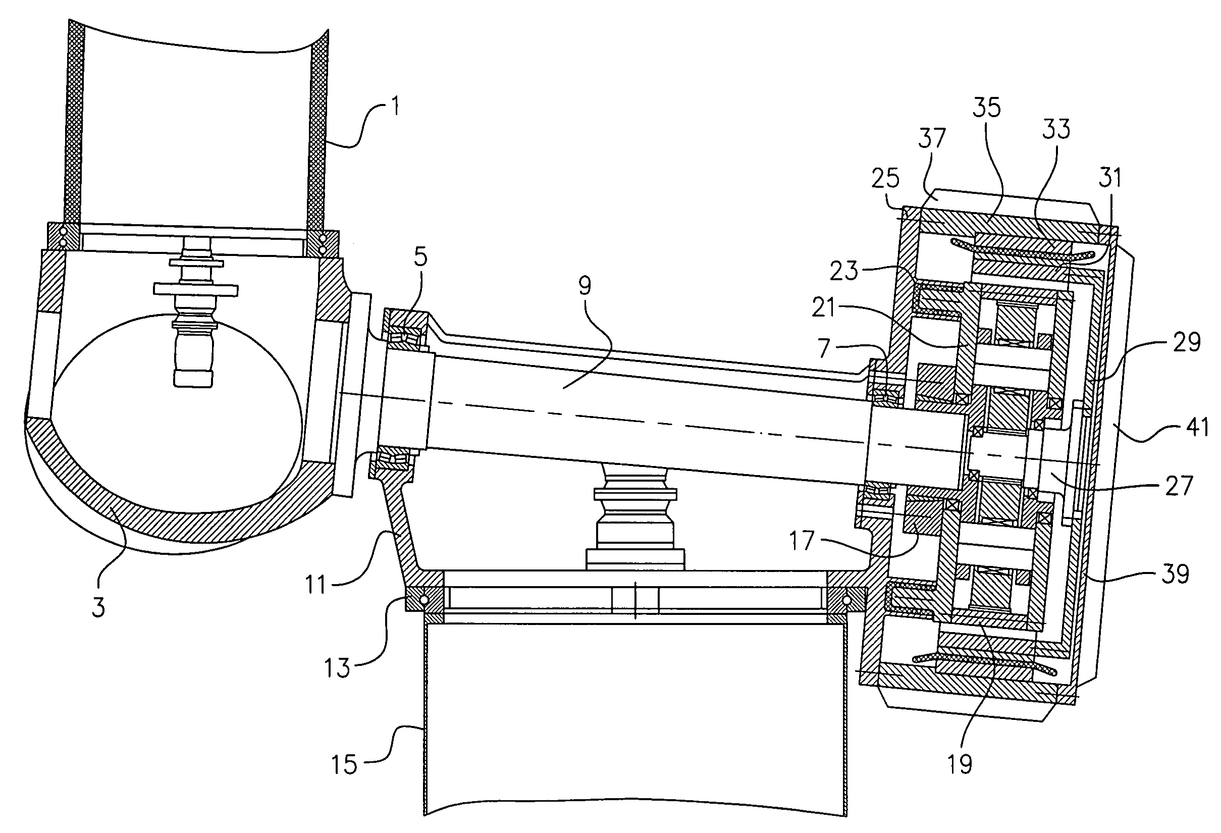
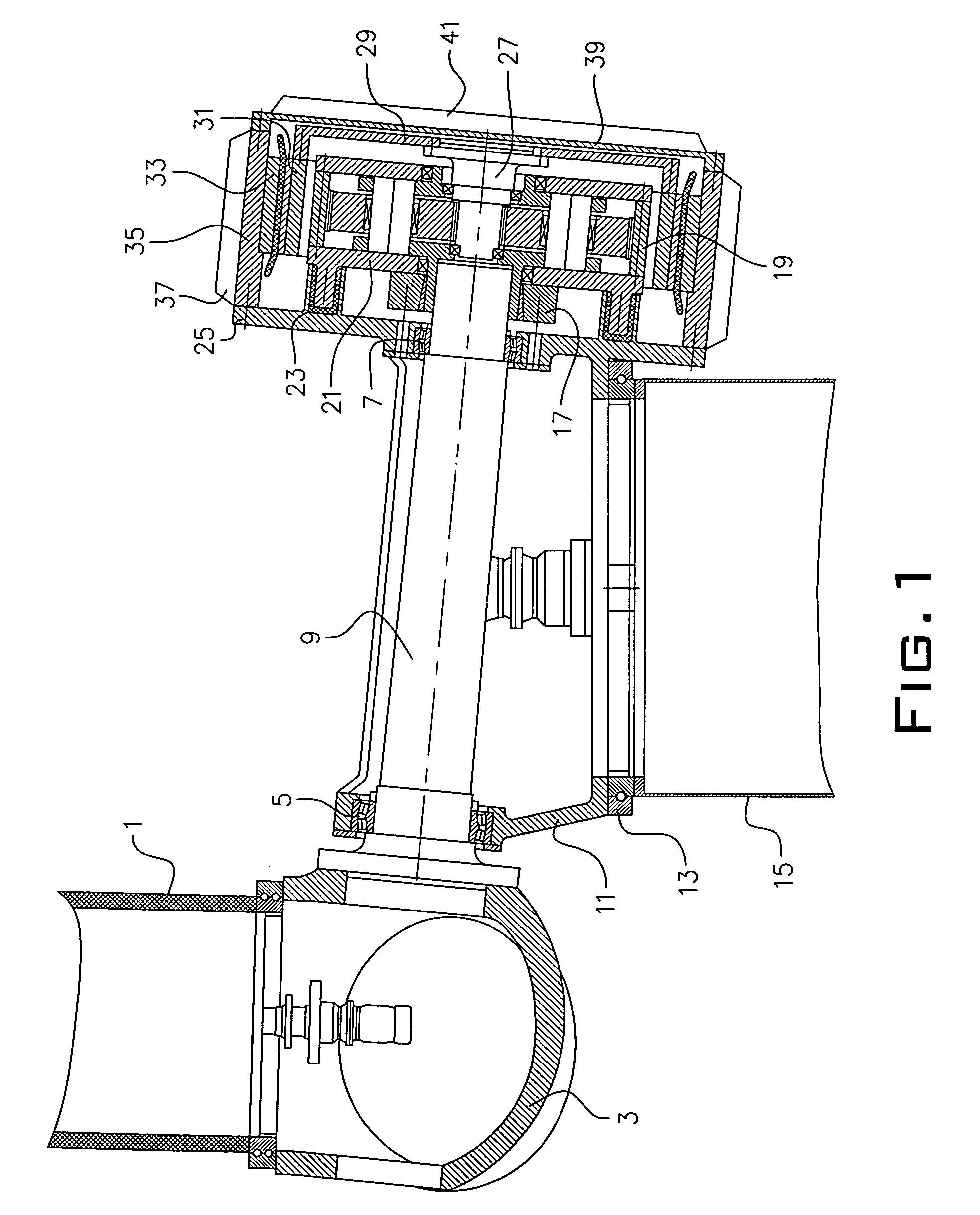
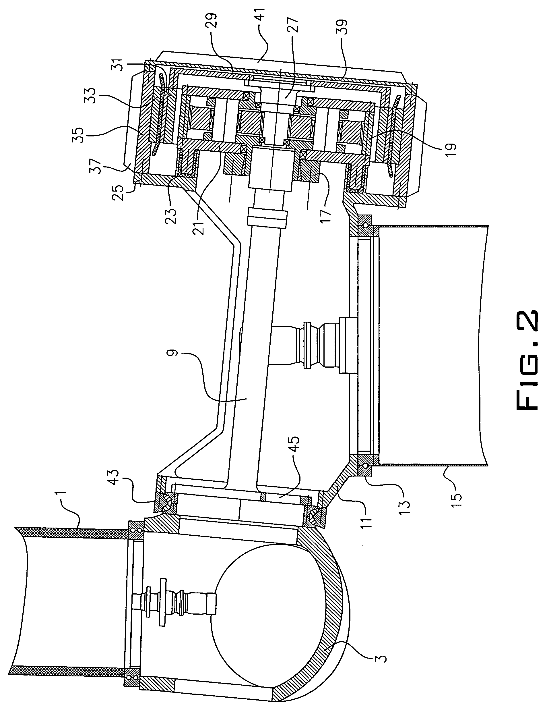
[0024]The wind energy installation rotor blades 1, only partly shown in FIG. 1, drive a hub 3 which also receives all the further force and momentum produced by the rotor. By means of a front rotor bearing 5 and a rear rotor bearing 7, a rotor shaft 9 is mounted and the rotor loads are transmitted to a machine support 11.

[0025]A vertical bearing 13 then transfers the loads into the wind energy plant tower 15. As a result, the external aerodynamic loads and mass loads of the rotor are introduced into the tower without having to be entirely or partly passed via the gear or generator. By means of a connecting element 17, e.g. a shrink ring, the gear 19 is connected in torque-resistant manner to the rotor shaft 9.

[0026]A gear casing 21 is supported by means of the elastic elements 23 with respect to a base plate 25. These elastic elements 23 ensure that torque surges are absorbed and structural deformations, as a result of external loads, do not lead to a loading of the tooth system or ...


PUM


Abstract

A wind energy plant comprising a rotor, a rotor shaft, a gear, and a generator, the generator embodied as a ring concentrically embracing the gear.

Description

PRIOR APPLICATIONS[0001]This §371 National Phase patent application bases priority on International Application No. PCT / DE2003 / 002722, filed on Aug. 13, 2003, which in turn bases priority on German Application No. DE 102 42 707.0, filed on Sep. 13, 2002.BACKGROUND OF THE INVENTION[0002]1. Field of the Invention[0003]The invention relates to a wind energy installation with a concentric gear and generator arrangement according to the preamble of the main claim.[0004]2. Description of the Prior Art[0005]Numerous different drive train arrangements are known for wind energy plants. In addition to gearless plants, most plants are built up from a combination of a gear and a generator. In wind energy plants, the gear and generator are conventionally arranged successively as individual components on a machine support. In the case of damage, this allows a simple replacement of these components, but the overall structure thereof is long and consequently heavy and cost intensive.[0006]In EP 811...

Claims


Application Information

Patent Timeline
Patent Type & Authority Patents(United States)
IPC IPC(8): F03D9/00F03D11/02F16H1/28H02K7/116H02K7/18
CPCF05B2220/7068F05B2260/2241F05B2260/40311F16H1/28F16H1/48H02K7/116H02K7/1838F03D15/00F03D9/25F03D15/10Y02E10/72F03D9/00H02K7/18
Inventor SIEGFRIEDSEN, SONKE
Owner AERODYN ENG GMBH
Why Eureka
Try Eureka