Three-dimensional video display and method for creating supply video supplied to three-dimensional video display

a three-dimensional video display and video supply technology, applied in the direction of optics, instruments, electrical equipment, etc., can solve the problems of viewer unsatisfactory, viewing position cannot be freely selected, and stereoscopic effect in the vertical direction cannot be obtained

Inactive Publication Date: 2007-02-20
SANYO ELECTRIC CO LTD
View PDF5 Cites 15 Cited by
  • Summary
  • Abstract
  • Description
  • Claims
  • Application Information

AI Technical Summary

Benefits of technology

[0010]In these configurations, a more effective function is produced in making a viewer recognize a stereoscopic video, as compared with that in a case where the lines respectively connecting the centers of the light emitters or the light transmitters and the centers of the pixel regions corresponding to the light emitters or the light transmitters are parallel to one another.
[0037]In such a configuration, the display video can be produced in such a setting that the longitudinal arrangement pitch of the pixels composing the recording pixel region is made narrower than the longitudinal arrangement pitch of the pixels composing the pixel region in a certain scene of the video, while the display video can be produced in such a setting that the longitudinal arrangement pitch of the pixels composing the recording pixel region is made wider than the longitudinal arrangement pitch of the pixels composing the pixel region in another scene of the video. Therefore, it is possible to make the viewer effectively recognize a stereoscopic video.

Problems solved by technology

However, a stereoscopic effect in the vertical direction cannot be obtained, with which a viewer is unsatisfied.
Accordingly, the viewing position cannot be freely selected, which is inconvenient.
However, it is a problem to make the viewer Z recognize a more real stereoscopic impression.

Method used


Image

  • Three-dimensional video display and method for creating supply video supplied to three-dimensional video display
  • Three-dimensional video display and method for creating supply video supplied to three-dimensional video display
  • Three-dimensional video display and method for creating supply video supplied to three-dimensional video display

Examples


embodiment 1

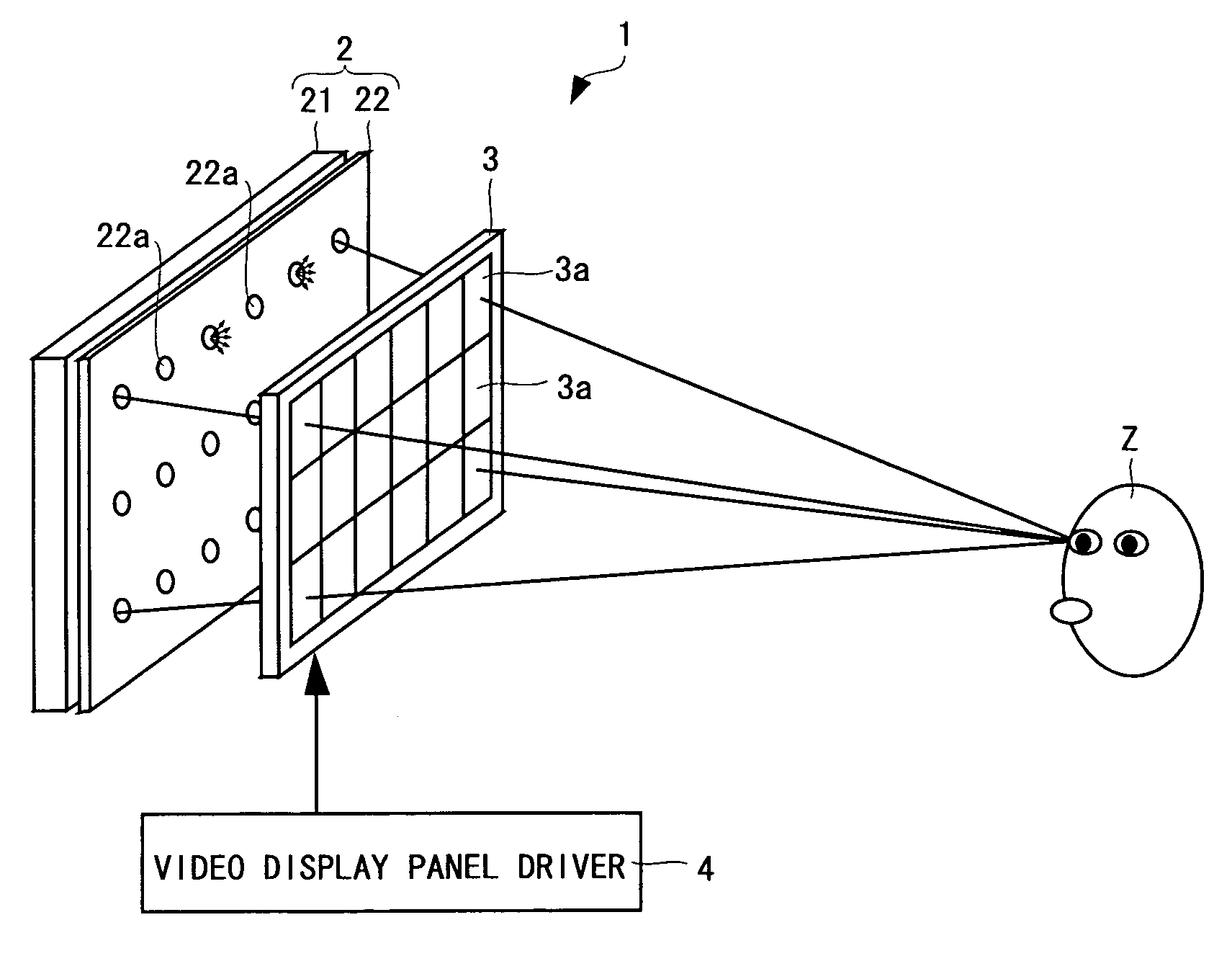
[0063]A stereoscopic video display according to a first embodiment of the present invention will be described on the basis of FIG. 1.

[0064]FIG. 1 is a cross-sectional view showing a stereoscopic video display 1. The stereoscopic video display 1 comprises a light source device 2, a transmission type liquid crystal display panel 3 provided on the side of light emission of the light source device 2, and a liquid crystal display panel driver 4 for driving the liquid crystal display panel 3.

[0065]The light source device 2 comprises a backlight 21 and a pinhole array plate 22. The pinhole array plate 22 has a plurality of pinholes 22a formed therein with predetermined spacing. A group of light beams is given to the liquid crystal display panel 3 from each of the pinholes 22a.

[0066]The liquid crystal display panel driver 4 feeds a pixel driving signal to the liquid crystal display panel 3, to form a pixel region 3a, composed of a plurality of pixels (e.g., 9 to 20 pixels in width and 3 to...

embodiment 2

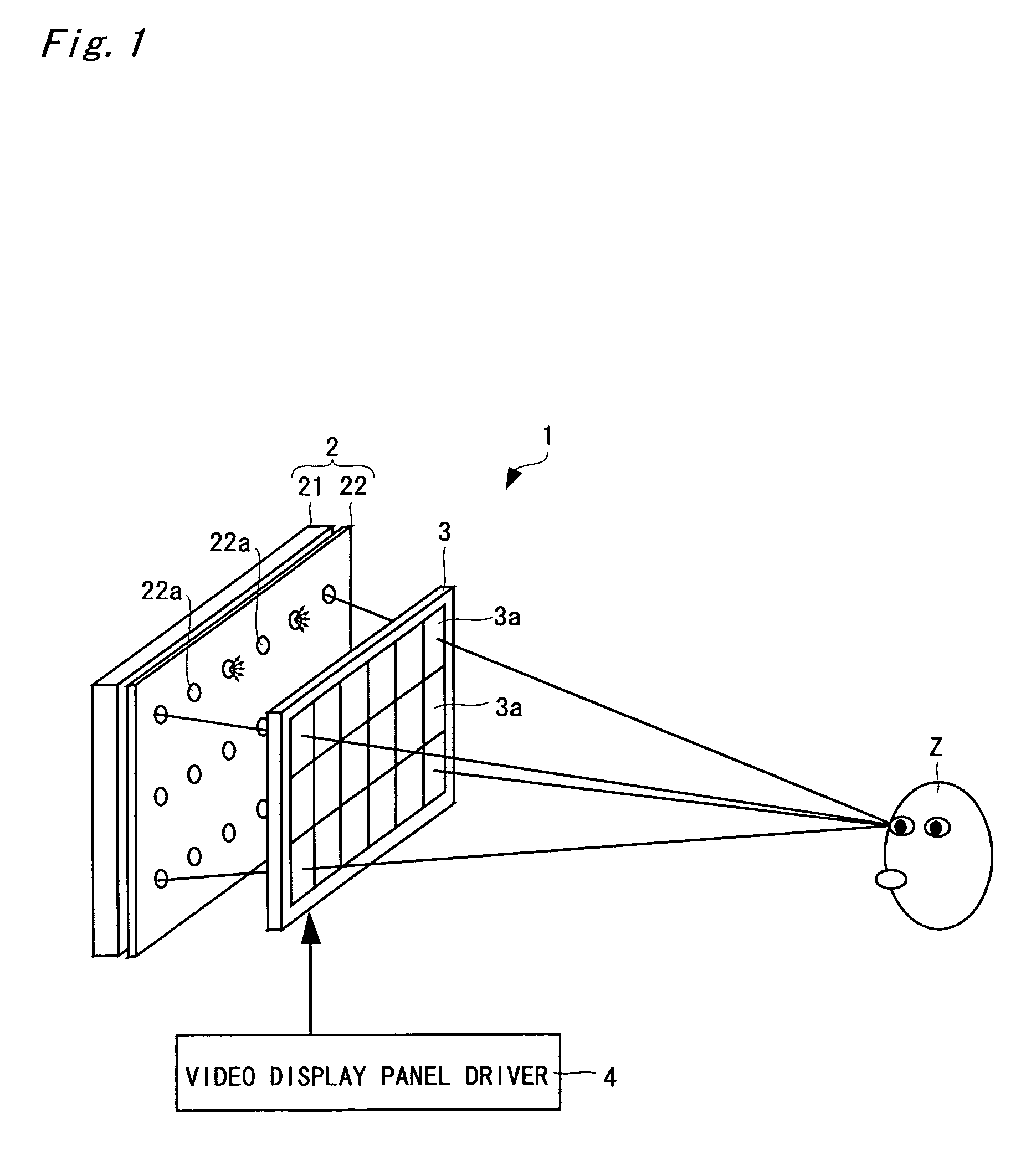
[0071]A stereoscopic video display according to a second embodiment of the present invention will be described on the basis of FIGS. 2 and 3. For convenience of illustration, the same constituent elements as the constituent elements described in the first embodiment are assigned the same reference numerals.

[0072]FIG. 2(a) is a cross-sectional view showing a stereoscopic video display 11, and FIG. 2(b) is a diagram for explaining the function thereof. The stereoscopic video display 11 comprises a light source device 5, a transmission type liquid crystal display panel 3 provided on the side of light emission of the light source device 5, and a liquid crystal display panel driver 4 for driving the liquid crystal display panel 3.

[0073]The light source device 5 comprises a backlight 21 and a pinhole array plate 23. The pinhole array plate 23 has a plurality of pinholes 23a formed therein with predetermined spacing. A group of light beams is given to the liquid crystal display panel 3 fro...

embodiment 3

[0078]A stereoscopic video display according to a third embodiment of the present invention will be described on the basis of FIGS. 4 to 6. For convenience of illustration, the same constituent elements as the constituent elements described in the first embodiment are assigned the same reference numerals.

[0079]FIG. 4(a) is a cross-sectional view showing a stereoscopic video display 12, and FIG. 4(b) is a diagram for explaining the function thereof. The stereoscopic video display 12 comprises a light source device 6, a transmission type liquid crystal display panel 3 provided on the side of light emission of the light source device 6, a liquid crystal display panel driver 4 for driving the liquid crystal display panel 3, and a liquid crystal shutter driver 7.

[0080]The light source device 6 comprises a backlight 21 and a liquid crystal shutter 24 having dot-shaped light transmission regions arbitrarily formable in its predetermined portions. In the liquid crystal shutter 24, light tra...


PUM

PropertyMeasurementUnit
unit areaaaaaaaaaaa
lengthaaaaaaaaaa
lengthaaaaaaaaaa

Abstract

There is provided a stereoscopic video display that enables a viewer to recognize a more real stereoscopic video.A light source device 2 comprises a backlight 21 and a pinhole array plate 22. A liquid crystal display panel driver 5 feeds a pixel driving signal to a liquid crystal display panel 3, to form a pixel region 3a composed of a plurality of pixels respectively corresponding to pinholes 22a. Each of the pixels composing the pixel region 3a controls an amount of light transmission with respect to a light beam in each direction from the corresponding pinhole 22a. Consequently, the intensity of the light beam in each direction is reproduced. Lines respectively connecting the centers of the pinholes 22a and the centers of the pixel regions 3a are not parallel to one another, and are so set as to cross at one point of a position corresponding to the standard distance between the video display panel 3 and a viewer Z. Therefore, the light beams are efficiently concentrated at a standard viewing position, thereby making it possible to make the viewer Z recognize a more real stereoscopic video.

Description

TECHNICAL FIELD[0001]The present invention relates to a stereoscopic video display using a so-called light beam reproduction system and a method of producing a supplied video utilized therefor.BACKGROUND ART[0002]As methods of realizing stereoscopic video display without requiring special glasses, a parallax barrier system, a lenticular lens system, and so on have been conventionally known. In the systems, right eye videos and left eye videos which have binocular parallax are alternately displayed on a display screen in a stripe shape. Accordingly, a stereoscopic effect in the horizontal direction is obtained. However, a stereoscopic effect in the vertical direction cannot be obtained, with which a viewer is unsatisfied. Further, outside a proper viewing position, such a phenomenon called reversed view that a left eye video is incident on the right eye, while a right eye video is incident on the left eye, for example, occurs. Accordingly, the viewing position cannot be freely select...

Claims


Application Information

Patent Timeline
Patent Type & Authority Patents(United States)
IPC IPC(8): G09G3/00G02B27/22G02F1/1335G02F1/13357H04N13/307H04N13/349
CPCG02B27/2214G02F1/1336H04N13/0402H04N13/0418G02B6/4298G02F1/133524G02F1/133526H04N13/0497H04N13/0409H04N13/0445G02F2001/133613H04N13/302H04N13/32H04N13/31H04N13/349H04N13/398H04N13/307G02F1/133613G02B30/27
Inventor HAMAGISHI, GOROMASHITANI, KENINOUE, MASUTAKAHIGASHINO, MASAHIRO
Owner SANYO ELECTRIC CO LTD
Why Eureka
Try Eureka