Plasma display and its driving method

a technology of display device and display panel, which is applied in the direction of instruments, static indicating devices, etc., can solve the problems of difficult to display such a change in luminance as smoothly as in a crt device, light emission gain, and luminance cannot be substantially reduced, and achieves superior performance.

Inactive Publication Date: 2007-02-20
PANASONIC CORP
View PDF15 Cites 9 Cited by
  • Summary
  • Abstract
  • Description
  • Claims
  • Application Information

AI Technical Summary

Benefits of technology

[0008]In consideration of the abovementioned problems, the aim of the present invention is to provide a PDP display device and driving method therefor, capable of offering superior performance during low-level gradation display when performing multi-level gradation display.
[0010]According to this driving method, because emission luminance of the subfield having the lowest relative luminance ratio is displayed using the light emission of only the initialization period and the write period, the discharges in each of the sustain period and erase period are unnecessary. Therefore, in the present invention, emission luminance in a subfield having a lowest relative luminance ratio is dramatically restricted to approximately half of the conventional emission luminance, and of 256 total gradation levels, low-level gradation changes from level 0 gradation to level 1 gradation display time can be displayed smoothly based on this lowered emission luminance.
[0012]According to this driving method, the illumination of the display area of the subfield having a relative luminance ratio corresponding to the lowest weight, is shared between two frames, and as a result, the amount of light emission in the subfield that has the lowest relative luminance ratio of a frame can be reduced to about one quarter of the conventional amount. Accordingly, when using this driving method, dark light emission during display from level 0 gradation to level 1 gradation can be displayed even more smoothly.
[0013]Further, if display is performed using the discharges of only the initializing and write periods in a subfield having the second smallest relative luminance ratio of the frame, in the two successive subfields, the light emission having the lowest relative luminance ratio, and the light emission having the next smallest relative luminance ratio are able to be performed more smoothly than conventionally in a dark display, and a superior low-level gradation display time is realized.
[0015]By this method, because the wall charge originating in the subfield having the lowest relative luminance ratio can be gradually initialized in the next subfield by the initializing discharge, and the occurrence of bright erroneous discharge can be effectively prevented, a smooth transition from the gradation display having the lowest relative luminance ratio to the next gradation display is possible, resulting in good display performance.

Problems solved by technology

A PDP display device having the above characteristics incurs the following problems during low-level gradation display.
However in a PDP display device, the luminance ratio of level 0 gradation and level 1 gradation is no less than 2 cd / m2, therefore it is difficult to display such a change in luminance as smoothly as in a CRT device.
In response to this problem, if the sustain pulse rate is set at a very low gradation setting, light emission gained by sustain pulses during the level 1 gradation display time can be restricted, however because light emission is left over from the initialization pulse, write pulse, and erase pulse, luminance cannot be substantially lowered.
Further, even if gradation display time is falsely attempted using error diffusion processing (dither method), error diffusion noise is noticeable on the screen because the gradation level is low, and rather than an effective error diffusion result being gained, a new problem of deterioration in picture quality arises.

Method used


Image

  • Plasma display and its driving method
  • Plasma display and its driving method
  • Plasma display and its driving method

Examples


first embodiment

[0034]1-1. Structure of the PDP

[0035]The PDP of the present first embodiment is made up of a PDP unit 1, and a panel driving unit 20 which drives the PDP unit 1.

[0036]FIG. 12 is a partial and cross-sectional perspective drawing of the main structure of an AC surface discharge PDP unit of the first embodiment. In the drawing, a vertical direction z corresponds to a PDP thickness direction, and horizontal directions x and y correspond to a plane which is parallel to the PDP unit panel surface. As shown in the drawing, the PDP unit 1 is made up of a front panel FP and a back panel BP which are arranged with their main surfaces facing each other.

[0037]A plurality of pairs of display electrodes 4 and 5 (scan electrodes 4 and sustain electrode 5) are arranged lengthwise along the x direction on the main surface of a front glass panel 2, which is the substrate of the front panel FP, and surface discharge is performed between the scan and sustain electrodes of each display electrode pair. H...

second embodiment

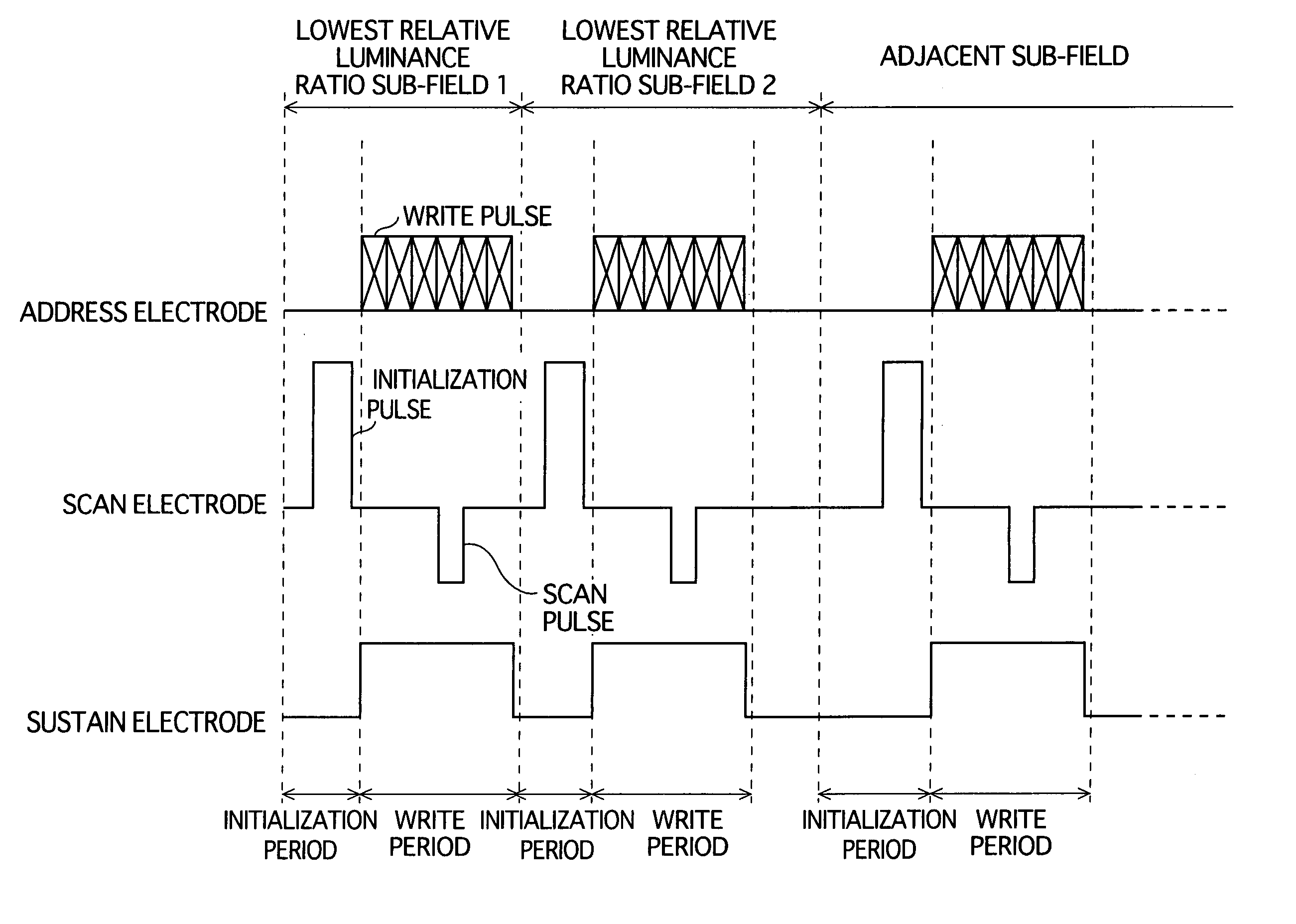
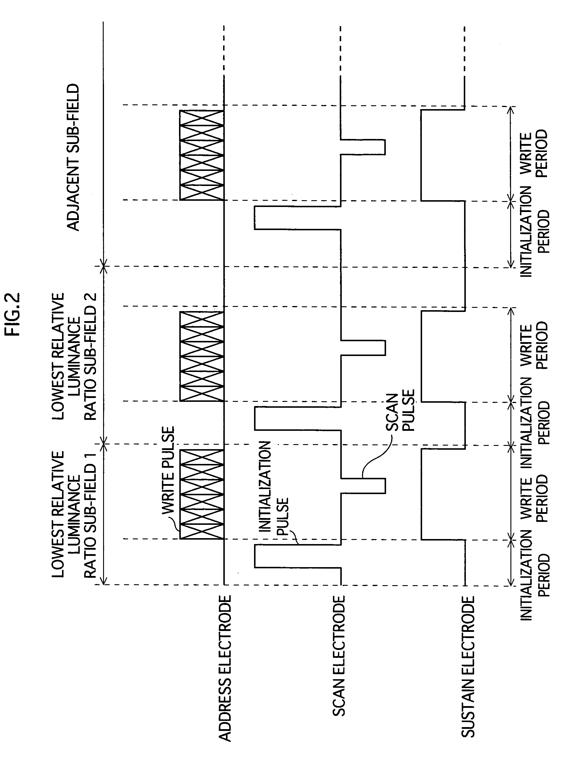
[0075]FIG. 2 is a drawing which shows subfields of the second embodiment during low gradation display.

[0076]In the second embodiment, one frame has a drive waveform process in which two consecutive subfields of the eight subfields with different assigned weights each consist of an initialization period and a write period, in a similar fashion to the first embodiment.

[0077]Further, in a subfield 2 (the latter of the two subfields), discharge is performed in the initialization period and the write period, in a similar fashion to the first embodiment.

[0078]On the other hand, in the preceding subfield 1 of a certain frame, in a low-level gradation display area in which the relative luminance ratio corresponds to the lowest weight, every second cell of a group of adjacent cells is illuminated, as shown in FIG. 3(a). Then, in the frame which follows after the subfield 2, the cells which were not illuminated in the previous low-level gradation display area are illuminated, as shown in FIG....

third embodiment

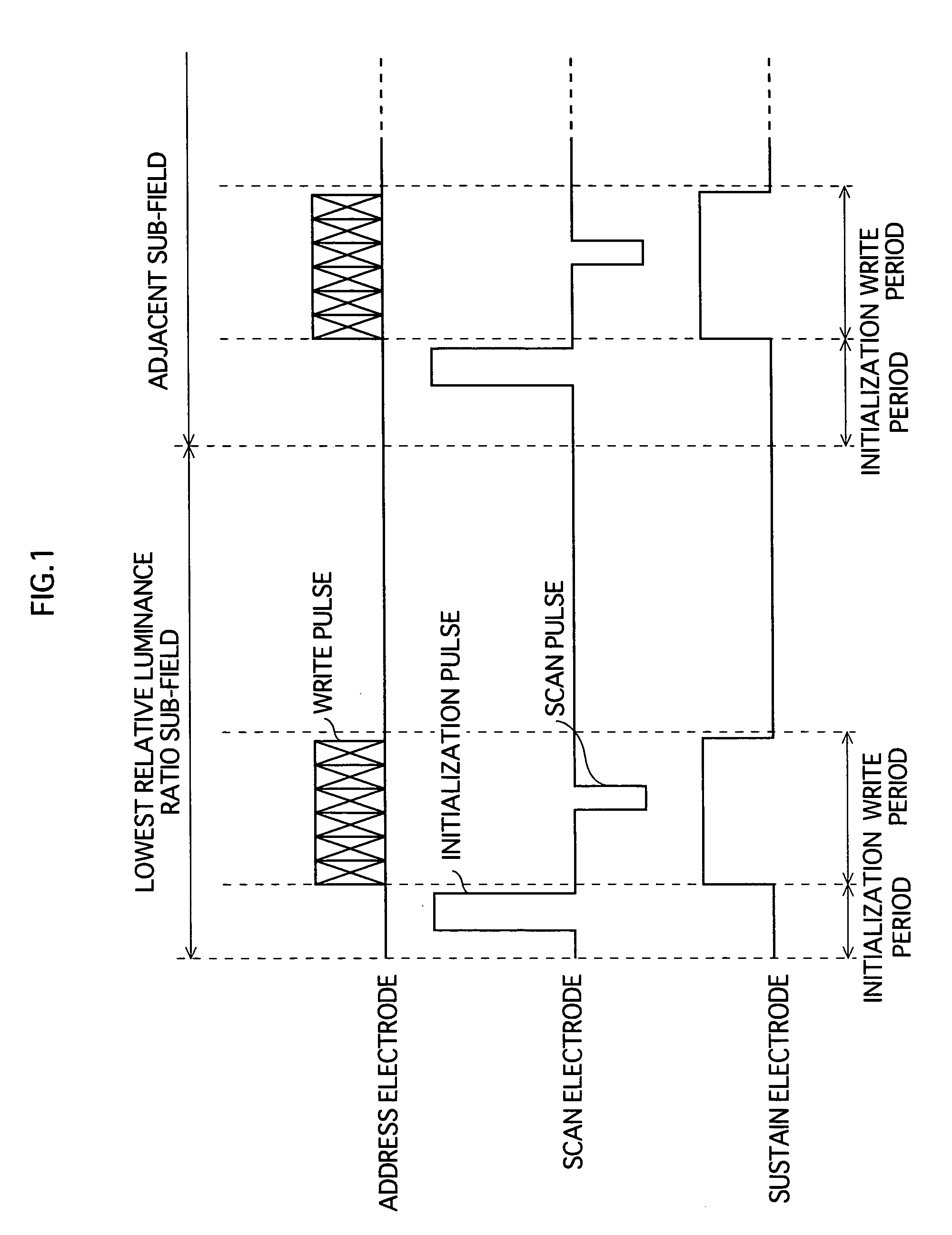
[0091]FIG. 6 is a drawing showing a subfield during low gradation display in the second embodiment.

[0092]In the drive waveform process of the third embodiment which is shown in the drawing, firstly, as in the first embodiment, the subfield in which the relative luminance ratio corresponds to the lowest weight consists of two periods, the two periods being the initialization period and the write period. The drive waveform process of the third embodiment also has a characteristic wherein an initialization pulse, which has an inclined accelerating section, is applied in the initialization period of the subfield following after the abovementioned subfield. Concerning the specific incline of the accelerating section, from actual results determined by the present inventors, a maximum incline of approximately 7.5V / μs is considered possible, though it is preferred that the incline be in a range of 1V / μs–3.5V / μs. The maximum value of the initialization pulse may be approximately 400V, which ...


PUM


Abstract

A PDP display apparatus driving method for performing multi-level gradation display by constituting one frame of a plurality of subfields assigned different weights, wherein in a subfield in which a relative luminance ratio corresponds to a lowest weight, display is performed according to discharges in two periods only, the periods being an initialization period and a write period.

Description

TECHNICAL FIELD[0001]The present invention relates to a plasma display panel display device and its driving method.BACKGROUND ART[0002]A plasma display panel (PDP) display device includes a PDP unit being composed of a thin front glass panel and a thin back glass panel arranged facing each other via a plurality of barrier ribs, having fluorescent layers of each of the colors red (R), green (G), and blue (B) applied between the barrier ribs, and discharge gas enclosed in a discharge space which is a gap between the two glass panels. A plurality of pairs of display electrodes, each pair consisting of a scan electrode and a sustain electrode, are formed on the front glass panel. Also, a plurality of address electrodes are aligned on the back glass panel, so as to be perpendicular to the display electrodes, the discharge space being between the address electrodes and display electrodes. In a subfield (which is described later), each of the electrodes is applied with pulses such as initi...

Claims


Application Information

Patent Timeline
Patent Type & Authority Patents(United States)
IPC IPC(8): G09G3/10G09G3/28G09G3/292G09G3/20G09G3/294G09G3/296G09G3/36
CPCG09G3/2037G09G3/2803G09G3/294G09G3/2927G09G2320/0271G09G2310/066G09G2320/0238G09G3/292G09G3/296
Inventor YAMADA, KAZUHIRO
Owner PANASONIC CORP
Why Eureka
Try Eureka