High performance catadioptric imaging system

a catadioptric and optical system technology, applied in the field of optical imaging, can solve the problems of poor surface quality, difficult manufacturing and extremely expensive, and inability to meet the requirements of microlithography exposure,

Inactive Publication Date: 2007-02-20
KLA TENCOR TECH CORP
View PDF50 Cites 7 Cited by
  • Summary
  • Abstract
  • Description
  • Claims
  • Application Information

AI Technical Summary

Problems solved by technology

Certain issues exist with designs similar to that presented in FIG. 1.
First, the field lens group may need to be physically located within a central hole in the large curved catadioptric element, which can make manufacturing very difficult and extremely expensive.
Second, the field lens elements in such a design may require at least one glued interface.
In the presence of wavelengths less then 365 nm, reliable glues that can withstand light intensity levels at an internal focus are generally unavailable.
Third, the lens elements in such a design may be located very close to a field plane, thereby requiring a high degree of, or nearly perfect, surface quality and bulk material quality to prevent image degradation.
Large diameter elements frequently make integration into an inspection system difficult and can increase manufacturing costs.
The design of FIG. 2 is relatively large, thereby generally requiring complicated optomechanical mounting of elements, especially in the catadioptric group.
Other optical arrangements have been developed to perform specimen inspection, but each arrangement tends to have certain specific drawbacks and limitations.
An all refractive objective design is difficult in this wavelength range because few glass materials having high transmission are effective for chromatic correction.
A small bandwidth may not be desirable for inspection applications due to limitation of available light power and increased interference from thin films on the surface being inspected.
This design approach can somewhat reduce the objective diameter, at the cost of increasing central obscuration, significantly degrading objective performance.

Method used


Image

  • High performance catadioptric imaging system
  • High performance catadioptric imaging system
  • High performance catadioptric imaging system

Examples


Embodiment Construction

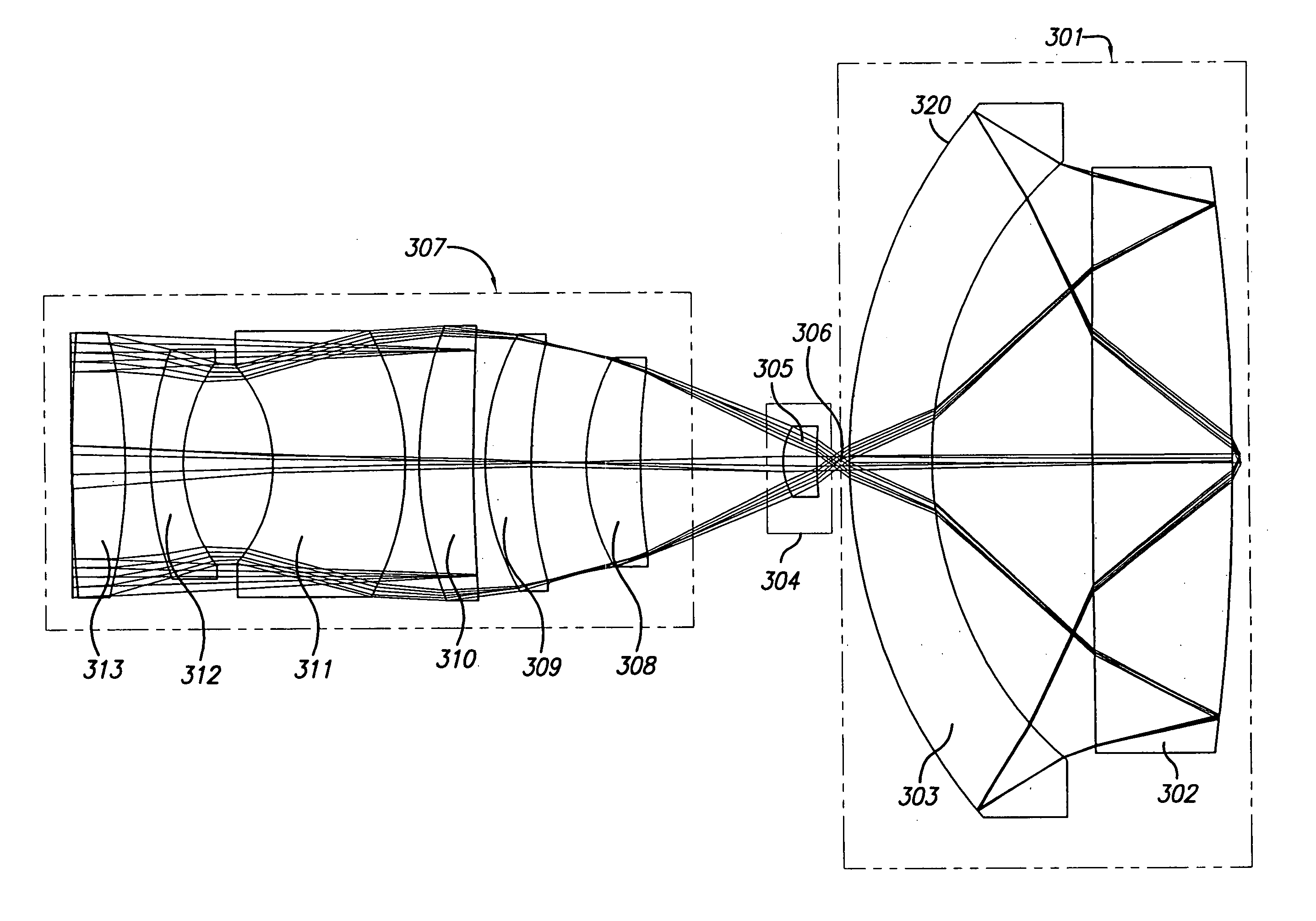
[0032]According to the present invention, there is provided a catadioptric objective corrected over a wavelength range from 285–320 nm using a single glass material, or in certain circumstances, more than one glass material to improve performance. One aspect of the objective design is shown in FIG. 3. The catadioptric objective as shown in FIG. 3 is optimized for broad-band imaging in the UV spectral region, namely approximately 0.285 to 0.320 micron wavelengths. The objective provides relatively high numerical apertures and large object fields. The inventive design presented uses the Schupmann principle in combination with an Offner field lens to correct for axial color and first order lateral color. As shown in the aspect presented in FIG. 3, the field lens group 305 is slightly displaced from the intermediate image 306 to obtain enhanced performance.

[0033]From FIG. 3, the catadioptric group 301 or Mangin mirror arrangement includes a Mangin mirror element 302. Mangin mirror eleme...


PUM

PropertyMeasurementUnit
wavelengthaaaaaaaaaa
diameteraaaaaaaaaa
sizeaaaaaaaaaa

Abstract

A reduced size catadioptric objective and system is disclosed. The objective may be employed with light energy having a wavelength in the range of approximately 190 nanometers through the infrared light range. Elements are less than 100 mm in diameter. The objective comprises a focusing lens group configured to receive the light energy and comprising at least one focusing lens. The objective further comprises at least one field lens oriented to receive focused light energy from the focusing lens group and provide intermediate light energy. The objective also includes a Mangin mirror arrangement positioned to receive the intermediate light energy from the field lens and form controlled light energy for transmission to a specimen. The Mangin mirror arrangement imparts controlled light energy with a numerical aperture in excess of 0.65 and up to approximately 0.90, and the design may be employed in various environments.

Description

[0001]This application claims the benefit of U.S. Provisional Patent Application Ser. No. 60 / 449,326, entitled “High Performance, Low Cost Catadioptric Imaging System,” filed Feb. 21, 2003.BACKGROUND OF THE INVENTION[0002]1. Field of the Invention[0003]The present invention relates generally to the field of optical imaging and more particularly to catadioptric optical systems used for microscopic imaging, inspection, and lithography applications.[0004]2. Description of the Related Art[0005]Many optical and electronic systems exist to inspect surface features for defects such as those on a partially fabricated integrated circuit or a photomask. Defects may take the form of particles randomly localized on the surface, scratches, process variations, and so forth. Such techniques and devices are well known in the art and are embodied in various commercial products such as those available from KLA-Tencor Corporation of San Jose, Calif.[0006]Specialized optical systems are required in ins...

Claims


Application Information

Patent Timeline
Patent Type & Authority Patents(United States)
IPC IPC(8): G02B17/08G02B21/02G03F7/20
CPCG02B17/0812G02B17/0856G02B21/04G03F7/70225G03F7/70341G02B17/0892
Inventor SHAFER, DAVID R.CHUANG, YUNG-HOARMSTRONG, J. JOSEPH
Owner KLA TENCOR TECH CORP
Why Eureka
Try Eureka