Unlock instant, AI-driven research and patent intelligence for your innovation.

Valve timing controller

a timing controller and valve technology, applied in the direction of valve drives, non-mechanical valves, machines/engines, etc., can solve the problems of increasing the number of parts, affecting the efficiency of valve timing control, so as to reduce the number of fluid passages and reduce the number of parts. , the effect of small torque variation

Active Publication Date: 2007-02-27
DENSO CORP +1
View PDF6 Cites 30 Cited by
  • Summary
  • Abstract
  • Description
  • Claims
  • Application Information

AI Technical Summary

Benefits of technology

This configuration enhances the responsivity of phase control to the advance side, allowing the vane rotor to quickly reach the target phase even with low hydraulic pressure and small torque variation, and reduces the number of parts by eliminating the need for check valves in retard passages.

Problems solved by technology

However, check valves are disposed in a retard supply passage and an advance supply passage that supply the working fluid to the retard hydraulic chamber and the advance hydraulic chamber, respectively, which in turn presents a problem of increasing the number of parts.
As a result, in the construction in which the advance control of valve timing is performed by the use of torque variation that the camshaft receives on the retard side, as shown in FIGS. 24A and 24B, when the cylinders increases in number to reduce torque variation applied to the camshaft on the retard side, in a case where the number of revolutions of the engine is small and where the pressure of the working fluid is low, there is a possibility that the responsivity of the phase control to the advance side will deteriorate or that the phase control to the advance side will not be performed. FIG. 24A is an example showing the torque variation of an in-line 4-cylinder engine and FIG. 24B is an example showing the torque variation of an in-line 6-cylinder engine.

Method used


Image

  • Valve timing controller
  • Valve timing controller
  • Valve timing controller

Examples


first embodiment

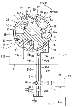
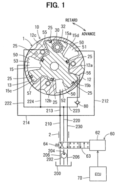
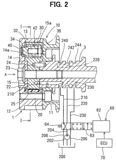
[0046]A valve timing controller in accordance with the first embodiment of the present invention is shown in FIG. 1 and FIG. 2. A valve timing controller 1 in accordance with the first embodiment is a hydraulic control type apparatus using a working oil as a working fluid and adjusts the valve timing of an intake valve.

[0047]As shown in FIG. 2, a housing 10 of a driving rotary body 10 has a chain sprocket 11 and a shoe housing 12. The shoe housing 12 includes shoes 12a, 12b, and 12c (see FIG. 1) as a partitioning part, a ring-shaped peripheral wall 13, and a front plate 14 opposed to the chain sprocket 11 with the peripheral wall 13 sandwiched between them, and is integrally formed with them. The chain sprocket 11 and the shoe housing 12 are coaxially fixed to each other by bolts 20. The chain sprocket 11 is coupled to a crankshaft (not shown) as the driving shaft of an engine by a chain (not shown), thereby having a driving force transferred thereto and rotating in synchronization ...

second embodiment

[0072]The second embodiment of the present invention is shown in FIG. 4 and FIGS. 5A and 5B. Here, the substantially same constituent parts as in the first embodiment are denoted by the same reference symbols.

[0073]As shown in FIG. 4, retard passages 300, 302 are formed in the direction of a rotary shaft in the boss 15d of the vane rotor 15. A retard passage 304 connects the retard passage 300 to the retard hydraulic chamber 51, and a retard passage 305 connects the retard passage 302 to the retard hydraulic chamber 52, and a retard passage 306 connects the retard passage 302 to the retard hydraulic chamber 53. The retard passages 300, 302, 304, 305, and 306 serve as the retard supply passage and the retard discharge passage, respectively.

[0074]Further, advance passages 310, 312 are formed in the direction of the rotary shaft in the boss 15d of the vane rotor 15. An advance passage 314 connects the advance passage 310 to the advance hydraulic chamber 55, and an advance passage 315 c...

third embodiment

[0080]The third embodiment of the present invention is shown in FIG. 6. In the third embodiment, sealing members 25 that seal gaps between the advance hydraulic chamber 56 and the retard hydraulic chambers 51, 52 are duplicated. The other construction is the substantially same as in the second embodiment.

[0081]When the vane rotor 15 receives torque variation on the retard side at the time of performing the phase control to the advance side, the check valve 90 prohibits the working oil from flowing out of the advance hydraulic chamber 56, so that the hydraulic pressure in the advance hydraulic chamber 56 becomes higher than the hydraulic pressure in the retard hydraulic chambers 55, 57. Hence, in the third embodiment, by duplicating the sealing members 25 that seal gaps between the advance hydraulic chamber 56 and the retard hydraulic chambers 51, 52, even if the hydraulic pressure in the advance hydraulic chamber 56 is increased, the working oil is prevented from leaking from the ad...


PUM


Abstract

A shoe housing receives a driving force from a crankshaft and a vane rotor rotates with a camshaft in combination. The vane rotor is received in the shoe housing in such a way as to freely turn. Each of the vanes of the vane rotor partitions each of three receiving chambers into a retard hydraulic chamber and an advance hydraulic chamber. A check valve is disposed in an advance supply passage. The check valve allows a working oil to flow from an oil pump through the advance supply passage to the advance hydraulic chamber and prohibits the working oil from flowing back from the advance hydraulic chamber through the advance supply passage to a drain.

Description

CROSS-REFERENCE TO RELATED APPLICATION[0001]This application is based on Japanese Patent Applications No. 2004-189656 filed on Jun. 28, 2004, and No. 2004-261905 filed on Sep. 9, 2004, the disclosure of which is incorporated herein by reference.FIELD OF THE INVENTION[0002]The present invention relates to a valve timing controller for changing a timing of opening or closing (hereafter referred to as “valve timing”) at least either the intake valve or the exhaust valve of an internal combustion engine (hereafter referred to as “engine”).BACKGROUND OF THE INVENTION[0003]Conventionally, there has been known a valve timing controller that includes: a housing for receiving the driving force of the crankshaft of an engine; and a vane rotor received in the housing and transferring the driving force of the crankshaft to a camshaft, and that turns the vane rotor toward a retard side and an advance side with respect to the housing by a working fluid pressure in a retard hydraulic chamber and a...

Claims


Application Information

Patent Timeline
Patent Type & Authority Patents(United States)
IPC IPC(8): F01L1/34F01L1/344
CPCF01L1/3442F01L2001/34426F01L2001/34479F01L2001/34469F01L2001/34456
Inventor YAOKO, SEIJIYAMADA, JUNTAKAHASHI, KINYAUSHIDA, MASAYASUMOHRI, MITOMUNOJIRI, TAKAO
Owner DENSO CORP