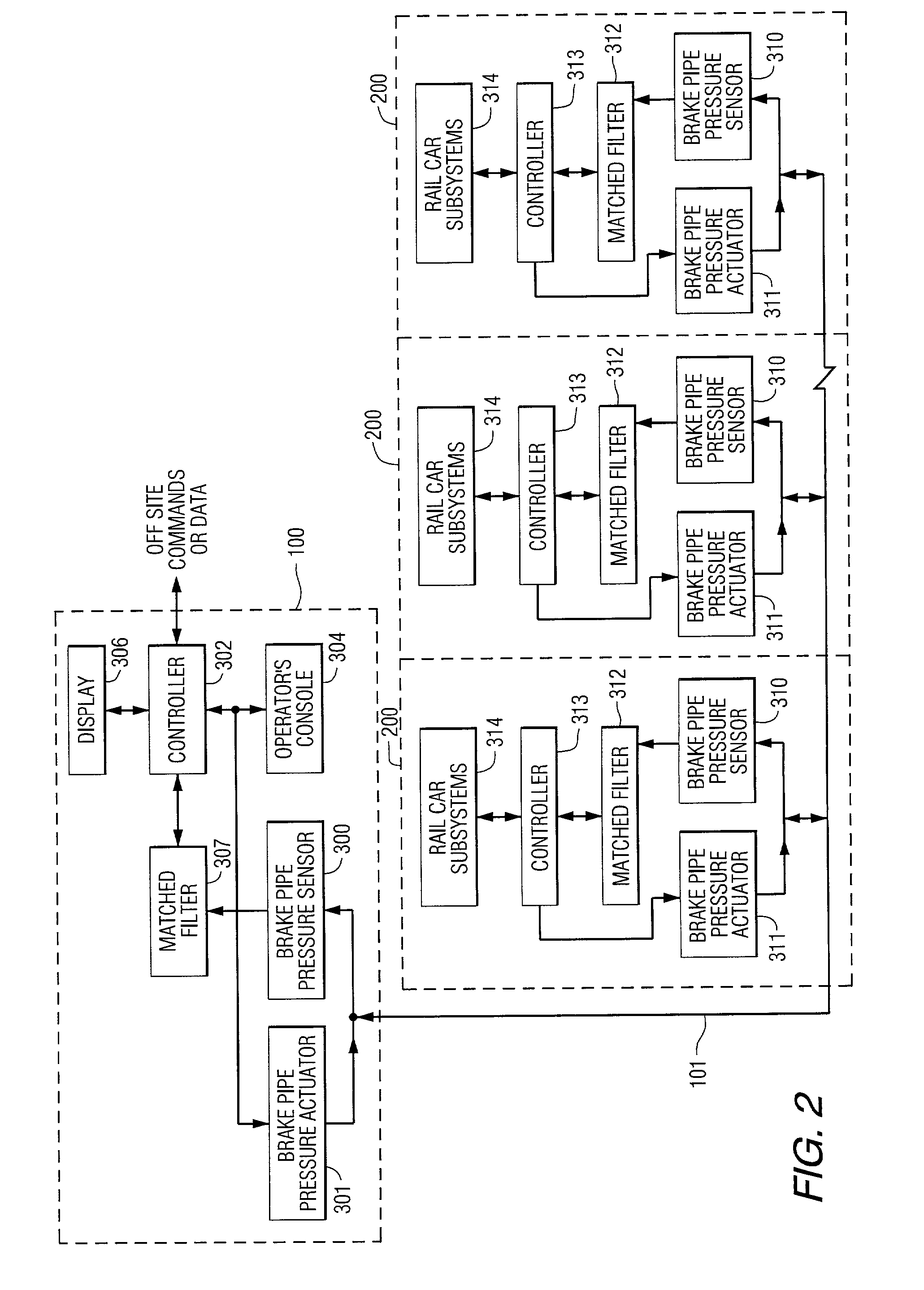
[0024]Due to the losses and frequency-dependent dispersive effects suffered by a pulse as it traverses the brake pipe, a
matched filter, operating in conjunction with the
pressure sensor, is the preferable detection device. The
matched filter at the receiving node detects the occurrence of a ping pattern by first analyzing the characteristics of the initial pulse or initial plurality of pulses (e.g.,
pulse duration, pulse width, leading and lagging edge slopes, time between pulses, energy in the pulse) and comparing these characteristics with known stored values (referred to as a first pulse template), that compensates for the brake pipe propagation effects. If the difference between the known and the received characteristics are less than a predetermined limit, then the
matched filter declares the occurrence of a ping pattern. These characteristic differences are then used to build a
pulse pattern template for application to subsequent pulses in the ping pattern. Thus the brake pipe propagation effects are compensated in the later pulses so that these pulses can be accurately decoded.
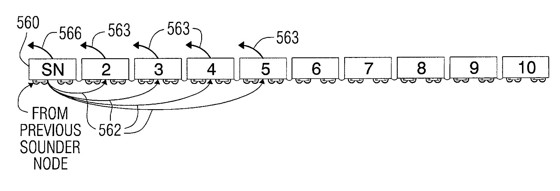
[0027]In one embodiment each sounder node group includes five railcars, with the fifth railcar serving as the sounder node to transmit the
pulse pattern to the next node group. In this way, the ping pattern propagation is limited to a length of five railcars and thus the propagation effects are minimized. Advantageously, it is then unnecessary to include a unique ping pattern template at each railcar matched filter. It is only necessary for the template to consider the propagation effects experienced as the pulse travels over five car lengths and thus considerably simplifies the design and operation of the pneumatic
pulse pattern communication
system.
[0030]Use of the brake pipe as a signaling communications path on the train avoids certain disadvantages associated with a wire-based or
radio frequency (RF) signaling systems as discussed above. In another embodiment, the pneumatic signally system works in conjunction with a radio-based system, providing initialization of the communications link and thereby avoiding the ambiguities that may be created when an RF link is utilized to link the train, as the brake pipe medium touches all the railcars in the train consist, and does not include railcars outside the train.
[0031]Further, one application of the teachings of the present invention obviates the need for RF communications devices on the train, as all communications between the locomotive and the railcars are carried over the brake pipe. This avoids the possibility that a railcar on an adjacent train might receive and erroneously respond to a
signal not intended for it. Also, degradation of the
radio frequency link due to man-made and natural objects encountered by the train as it travels along the rails is avoided.
[0033]Low brake
reservoir pressure is avoided by the present invention because relatively small pressure variations (the ping pattern pressure pulses)
signal brake applications. Both service brake applications and
emergency brake applications can be initiated by a ping pressure pattern according to the present invention. Thus the brake pipe is not exhausted for
emergency brake applications and both service and
emergency brake applications result in only slight brake pipe pressure reductions. Instead of using the brake pipe pressure to
signal a brake application, a specified pneumatic ping pattern is recognized at each railcar and instructs the railcar to immediately apply a predetermined
brake pressure to the railcar brakes. In yet another embodiment, the actual
brake pressure value (i.e., the amount of braking force to be applied) is included within the information conveyed by the ping pattern, providing the train operator with improved control over the braking process. Since the brake pipe
reservoir pressure is not exhausted during braking commands, the
reservoir pressure is available for repeated brake applications.
Train safety and handling is therefore improved.
[0034]As will be discussed further herein below, the present invention also teaches a train linking or ordering process that is faster (less than five minutes in one embodiment), more accurate and more reliable than prior art linking techniques discussed above. Use of the brake pipe
communications system to order the train cars also avoids the problem of linking any cars from a nearby train that respond to a linking RF signal, since signals on the brake pipe are received only by railcars within the train. Also, the
propagation time of the pneumatic ping pattern along the brake pipe provides a mechanism to estimate the distance between the sounder node and the receiving node.

