Diode detecting circuit

a detection circuit and diode technology, applied in the direction of pulse generators, pulse techniques, amplitude demodulation, etc., can solve the problem that bias voltages cannot be applied to diodes

Inactive Publication Date: 2007-02-27
FUJITSU SEMICON LTD
View PDF1 Cites 6 Cited by
  • Summary
  • Abstract
  • Description
  • Claims
  • Application Information

AI Technical Summary

Problems solved by technology

However, the diode detecting circuit 20 of FIG. 2 has a problem in that bias voltages cannot be applied to the diodes 21 and 24.
Moreover, since it is generally difficult to form a diode having a low threshold voltage within an integrated circuit (IC) chip, individual diodes must be used to produce a diode detecting circuit using an IC chip.

Method used


Image

  • Diode detecting circuit
  • Diode detecting circuit
  • Diode detecting circuit

Examples


Embodiment Construction

[0026]Embodiments of the present invention will be explained below with reference to the drawings. However, these embodiments are not intended to limit the technical scope of the present invention.

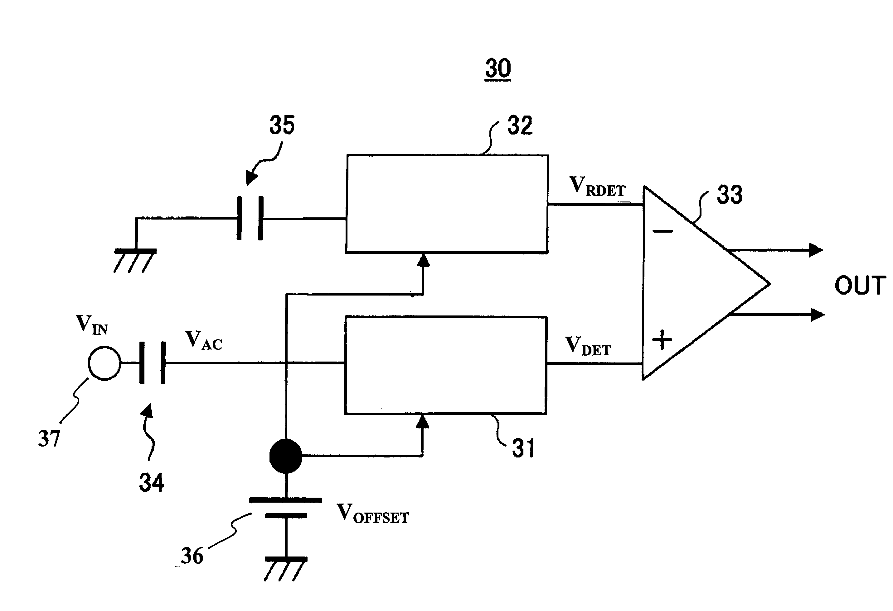
[0027]FIG. 3 is a block diagram of a diode detecting circuit 30 in accordance with an embodiment of the present invention. The diode detecting circuit 30 of FIG. 3 has a first diode detecting unit 31, a second diode detecting unit 32, a differential amplifier 33, a first input capacitor 34, a second input capacitor 35, a constant voltage source 36, and an input terminal 37.

[0028]An input voltage signal VIN is applied to the input terminal 37. The first input capacitor 34 shifts the input voltage signal VIN via capacitance coupling, and supplies an alternating input voltage signal VAC to the first diode detecting unit 31. The first diode detecting unit 31 comprises a diode detector of, for example, a half-wave rectifying type, both-wave rectifying type, bridge rectifying type, or both-wave ...


PUM


Abstract

A diode detecting circuit which cancels temperature dependence of a detecting diode so as to obtain highly sensitive detection. The diode detecting circuit has a first diode detecting unit in which a first diode detects an input signal biased by a bias voltage, a second diode detecting unit in which a second diode receives the bias voltage, and an output unit which compares an output from the first diode detecting unit with an output from the second diode detecting unit.

Description

[0001]This application claims priority from Japanese Patent Application Serial No. 2004-206333 of shinji SAITO filed Jul. 13, 2004. The entirety of that patent application is incorporated herein by reference.BACKGROUND OF THE INVENTION[0002]1. Field of the Invention[0003]The present invention relates to a diode detecting circuit for detecting an electromagnetic wave signal.[0004]2. Description of the Related Art[0005]A radio communication apparatus for detecting an electromagnetic wave signal of a particular frequency use a receiving apparatus. In order to start the receiving operation, the receiving apparatus determines whether the radio signal of the particular frequency to be received exists. In recent years, such radio communication apparatuses are typically required to have the capability of detecting a faint radio signal. Moreover, a need has arisen to provide a detecting circuit for such apparatuses that has a higher sensitivity, but that is available at a low price and has l...

Claims


Application Information

Patent Timeline
Patent Type & Authority Patents(United States)
IPC IPC(8): H03D3/02
CPCH03D1/10H03D2200/0096
Inventor SAITO, SHINJI
Owner FUJITSU SEMICON LTD
Why Eureka
Try Eureka