Enhanced rapid thermal processing apparatus and method

a technology of rapid thermal processing and equipment, applied in the field of rapid thermal processing, can solve the problems of impaired device functionality, device size and junction depths have progressively decreased, and difficulties in the use of isothermal rtp, so as to improve the uniformity of bulk temperature increase

Active Publication Date: 2007-02-27
MATTSON TECHNOLOGY +1
View PDF23 Cites 40 Cited by
  • Summary
  • Abstract
  • Description
  • Claims
  • Application Information

AI Technical Summary

Benefits of technology

[0017]In a continuing aspect of the present invention, an apparatus and associated method are described for heat treating at least one substrate having opposing first and second major surfaces which define a configuration of lateral extents of the substrate that is delimited by a peripheral edge configuration. The workpiece is received in a chamber interior that is defined by a processing chamber. A first heating configuration is in thermal communication with the chamber interior for emitting a pre-heating irradiance for inducing a bulk temperature rise of the workpiece progressively during a preheating interval such that changing a relative positional relationship, between the substrate and the first heating configuration, changes an intensity profile of the pre-heating irradiance across the lateral extents of the substrate. A manipulation arrangement is provided for elevationally moving the substrate and / or reflector during the preheating interval to change the intensity profile of the pre-heating irradiance across the lateral extents of the substrate in a way which enhances uniformity of the bulk temperature increase across the configuration of lateral extents of the substrate and for moving the substrate to a treatment position at a treatment station for exposure to a flash irradiance. A second heating configuration is in thermal communication with the chamber interior for emitting the flash irradiance to produce a substantially instantaneous increase in a surface temperature of a selected one of the first and second major surfaces of the substrate.

Problems solved by technology

As device sizes and junction depths have progressively decreased with successive generations, difficulties have come to light with respect to the use of isothermal RTP.
Such diffusion can result in impaired functionality of the device, in view of reduced feature sizes.
In addition to the aforedescribed difference with respect to diffusion effects, each form of RTP introduces other unique problems and opportunities with respect to its application.
It is submitted that this approach may be unduly complex in its need for an additional heat source that requires precision control.
It is considered that this approach is generally problematic for the reason that the radiated energy that is returned is simply not sufficient to compensate for the edge cooling effect caused by a combination of radiative, conductive and convective heat loss.
Applicants recognize that these support posts, unfortunately, in isothermal RTP, will generally produce cold spots on the opposing surface of the workpiece.
The patent, however, does not address this problem, as will be further discussed at an appropriate point below.
Further, the reflective surface extends under the wafer and it is considered that this reflector would interfere with a double-sided heating implementation.
Hence, it is submitted that they are not well-suited for use in RTP processes, since these configurations will absorb energy from the heating arrangement and continue to reradiate thermal energy onto the workpiece edge, even after the heating arrangement is shut down.
That is, there is no mechanism for producing reflection of the heat source energy onto the peripheral edge of the workpiece.
Such structures would introduce problematic shadowing if any attempt were made to illuminate the bottom surface of the workpiece, as illustrated in the views of these figures.

Method used


Image

  • Enhanced rapid thermal processing apparatus and method
  • Enhanced rapid thermal processing apparatus and method
  • Enhanced rapid thermal processing apparatus and method

Examples


Embodiment Construction

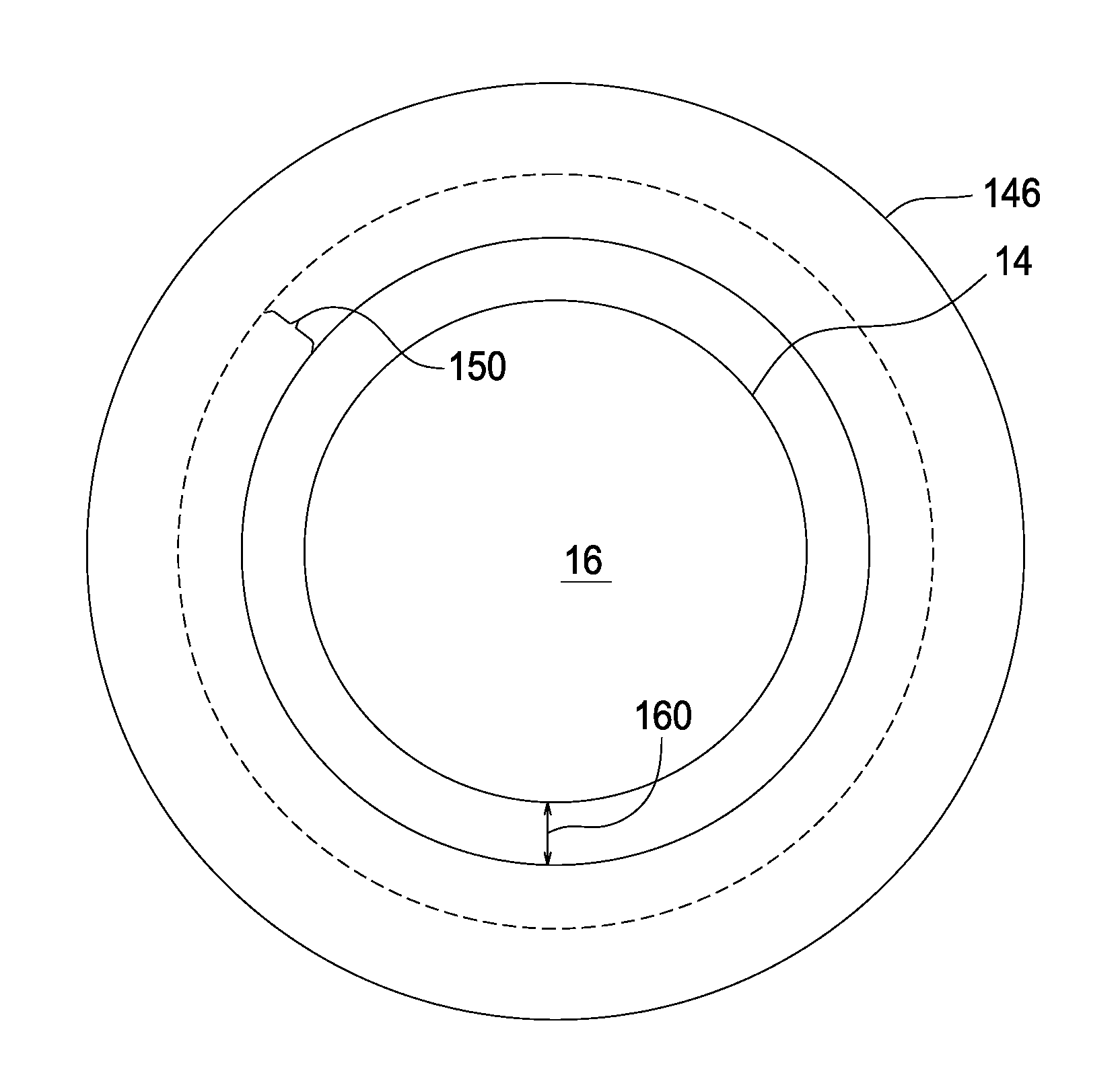
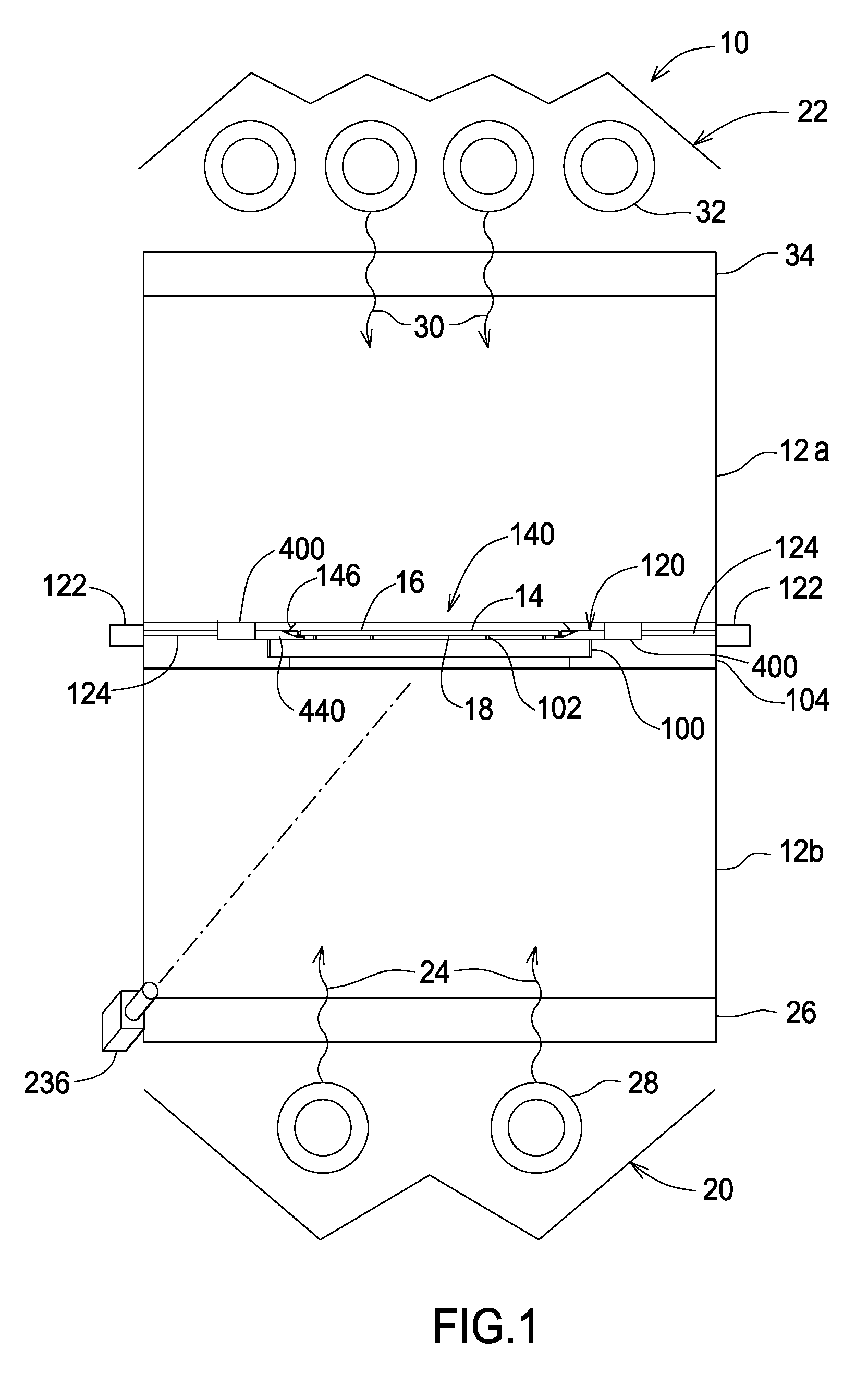
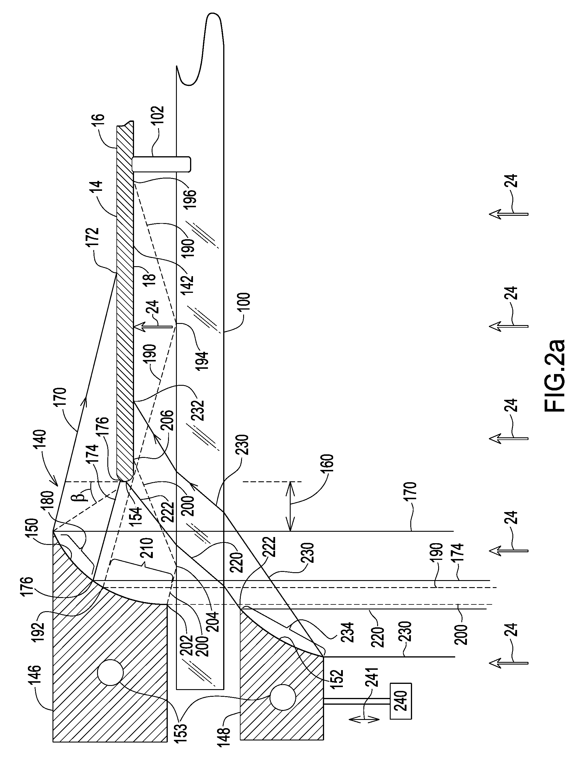
[0035]The following description is presented to enable one of ordinary skill in the art to make and use the invention and is provided in the context of a patent application and its requirements. Various modifications to the described embodiments will be readily apparent to those skilled in the art and the generic principles herein may be applied to other embodiments. Thus, the present invention is not intended to be limited to the embodiment shown but is to be accorded the widest scope consistent with the principles and features described herein including alternatives, modifications and equivalents, as defined within the scope of the appended claims. It is noted that the drawings are not to scale and are diagrammatic in nature in a way that is thought to best illustrate features of interest. Further, like reference numbers are applied to like components, whenever practical, throughout the present disclosure. Descriptive terminology such as, for example, uppermost / lowermost, right / le...


PUM

PropertyMeasurementUnit
distanceaaaaaaaaaa
angleaaaaaaaaaa
timeaaaaaaaaaa

Abstract

A heating arrangement heats a first major surface of a workpiece with an illumination energy such that a first portion of the illumination energy is directly incident upon the first major surface of the workpiece and a second portion of the illumination energy is directed such that, at least initially, the second portion would miss the first major surface. A reflector, having a central opening, reflects at least some of the second portion of the illumination energy onto the peripheral edge region of the workpiece for preheating compensation. The reflector is configured for shadow-free exposure of a second, opposing major surface of the workpiece to a flash heating energy. A workpiece manipulation arrangement is described to provide for dynamic preheating movement to vary a heating profile across the workpiece and, thereafter, move the workpiece to a flash heating position. Automatic workpiece centering is featured by the manipulation arrangement.

Description

BACKGROUND OF THE INVENTION[0001]The present invention is generally related to the field of Rapid Thermal Processing and, more particularly, to techniques and apparatus for enhancing uniformity in Rapid Thermal Processing.[0002]The prior art has developed a number of approaches in the use of Rapid Thermal Processing (RTP) for purposes of producing state-of-the-art devices. Such devices include, for example, semiconductor chips, solar cells and nanoparticle materials. RTP has been found to be particularly useful following ion implantation processes applied to a substrate or workpiece, in which the implanted dopant atoms are left in interstitial sites where they are electrically inactive. RTP is applied with the intention of repairing the damage to the crystal lattice structure and to move dopants to lattice sites to electrically activate these dopants.[0003]One form of RTP essentially uses isothermal heating in which radiant energy is applied for a time duration and at a cooperating ...

Claims


Application Information

Patent Timeline
Patent Type & Authority Patents(United States)
IPC IPC(8): A21B2/00C23C16/00
CPCH01L21/68728H01L21/67115
Inventor CAMM, DAVEKRASNICH, MIKEBUMBULOVIC, MIADENDETS, SERGIYMCCOY, STEVE
Owner MATTSON TECHNOLOGY
Why Eureka
Try Eureka