System and method for controlling generation over an integrated wireless network

a technology of integrated wireless communication and system, applied in non-electric variable control, process and machine control, instruments, etc., can solve problems such as inability to meet customer requirements, so as to overcome inadequacies and deficiencies, and reduce system demand

Inactive Publication Date: 2007-02-27
LANDISGYR TECH
View PDF16 Cites 253 Cited by
  • Summary
  • Abstract
  • Description
  • Claims
  • Application Information

AI Technical Summary

Benefits of technology

[0029]In another embodiment, the CP energy management controller may compare the initial total metered demand reduction with a specified demand reduction, and if the initial demand reduction is less than the specified demand reduction, the CP energy management controller automatically initiates a second round of demand reductions. With this alternative embodiment, if the initial demand reduction exceeds the specified demand reduction, the CP energy management controller would issue a control signal out to selected transceivers allowing their generators to adjust power output, thereby fine tuning the actual demand reduction to be substantially equal to the specified demand reduction requested by the control room operators.

Problems solved by technology

One of the well known difficulties in providing electricity to customers is precisely matching the aggregate amount of electricity consumed by all of the customers on an instantaneous basis with the amount of electricity generated and / or purchased by the providing electric utility or other responsible organization.
That is, at any instant in time, the electric utility or other responsible organization must provide exactly the amount of electricity used by all of the customers (plus the associated transmission system losses).
Failure by the electric utility or other responsible organization to exactly match the electric demand of their customers with the supply (generation and purchases), during every instant in time, may have very undesirable consequences should the mismatch become significant.
When significant mismatches between demand and supply occur, distortions in the electric system frequency occurs.
Furthermore, other electricity characteristics may be undesirably distorted, such as voltage, such that other types of protective relays begin to operate.
For example, if the electric utility or other responsible organization loses a generator in an unplanned manner, the electric system demand will exceed supply (because the supply decreases when the generator shuts down).
Although the action of the frequency sensitive relays effectively arrests the undesirable frequency decay, thereby saving the energy delivery system from a more severe decay in frequency and other undesirable associated problems, those customers that were disconnected are impacted in an undesirable manner.
The affected customers are inconvenienced when they are disconnected from the energy delivery system, and the affected customers did not volunteer to be selected as participants in the load shedding scheme.
Furthermore, the electric utility or other responsible organization loses the associated sales to the affected customers, thereby negatively impacting the electric utility's or other responsible organization's revenue stream.
However, this is not a very effective technique for reducing demand.
The 6 kW decrease in demand does not provide a meaningful demand reduction because the demand decrease is too small to be of practical help in matching demand of the entire system with supply.
Also, the cost of the RF receivers is not likely justifiable for so little of a demand reduction.
However, such energy demand reduction systems employing a plurality of RF controlled load blocks have numerous problems and deficiencies.
Once a load block is established by configuring an RF communication network to provide a unique shut-off signal, and after a sufficient number of selected appliances are fitted with RF receivers responsive to the shut-off signal, it is difficult to revise, update and / or modify the load block.
Furthermore, making significant changes to an established load block will take a considerable amount of time to implement.
Furthermore, there is no way to ascertain the failure of an RF receiver or the associated appliance control equipment.
Another problem associated with conventional RF controlled load blocks arises from the statistical nature of loads serviced by an electric power distribution system.
Furthermore, the thermostat settings will not be the same for all of the residences.
The electric utility or other responsible organization cannot know with certainty exactly how much load is shut off when the shut-off signal is sent out to the RF receivers.
Another related problem arises from the nature in which the loads are metered (measured).
However, five air conditioning units not part of the load block may cycle on at substantially the same time that the shut-off signal is transmitted to the load block (a probable event if the substation is providing service to a large number of homes on a hot day).
But, the electric utility or other responsible organization will not know the exact amount of demand reduction realized when the load block is shut off.
Yet another problem with demand reduction systems employing fixed-size load blocks is that it is difficult to readjust changes made in demand, or to fine-tune the demand changes actually realized.
Thus, a load block designed to statistically provide a 10 MW demand reduction cannot be easily reconfigured to provide a 12 MW demand reduction.
Furthermore, if a 10 MW demand reduction is desired, the load block designed to statistically provide a 10 MW demand reduction will probably never provide exactly a 10 MW demand reduction.
If, for example, the load block provides an actual load reduction of 9 MW, there is no convenient and effective mechanism to fine tune the energy demand reduction system or the load block such that an additional 1 MW demand reduction can be ordered.
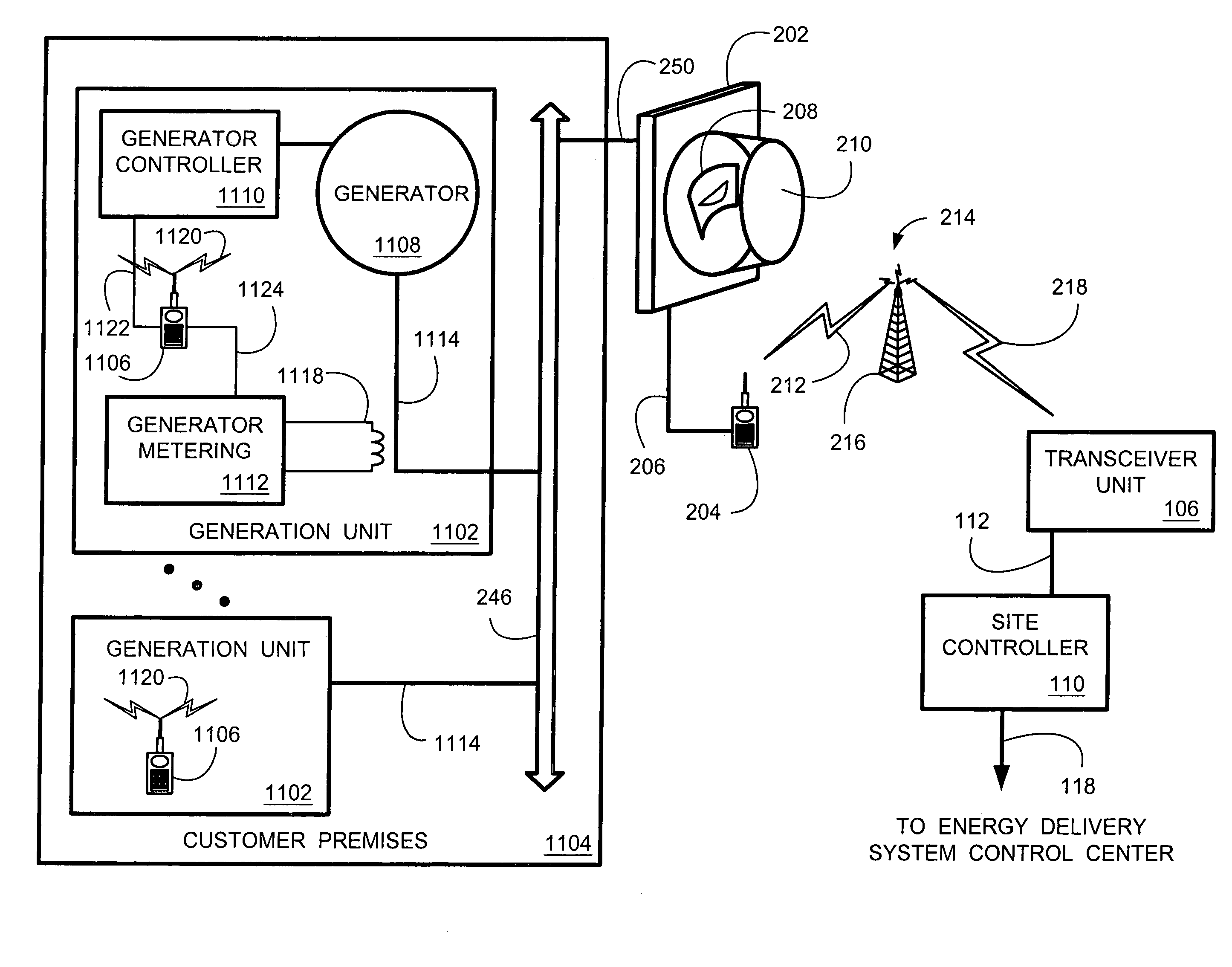
Generation is tantamount to a negative load (loads consume electricity, generators provide electricity).
Generally, stand-by generator fuel costs and operating costs are sufficiently high that the customer prefers to purchase electricity from the electric utility or other responsible organization.
Furthermore, since the electric utility or other responsible organization does not own or control the stand-by generator(s), the stand-by generator(s) can not be conveniently and quickly brought on line by the electric utility or other responsible organization when needed to reduce demand.
However, there is no guarantee that the stand-by generator(s) will be brought on line in a timely manner, nor at a desirable generation level, since the electric utility or other responsible organization is not in direct control of the generator.
Thus, a heretofore unaddressed need exists in the industry for providing a demand reduction and control system that accurately indicates the true amount of demand reduction realized when a shut-off signal is transmitted.
Also, there is a heretofore unaddressed need in the industry to provide a demand reduction and control system that provides for real time adjustment of demand on an appliance-by-appliance basis.
There is also a heretofore unaddressed need in the industry to automatically detect failure of RF receivers so that repairs can be initiated.
Furthermore, there is an unaddressed need to control stand-by generators.

Method used


Image

  • System and method for controlling generation over an integrated wireless network
  • System and method for controlling generation over an integrated wireless network
  • System and method for controlling generation over an integrated wireless network

Examples


Embodiment Construction

a. Overview of the Intelligent Network Demand Control System

[0046]In general, the present invention relates to a system and method for providing an electric utility or other responsible organization direct control over selected customer loads such that the controlled loads are selectively shut off during periods of time when the electric utility or other responsible organization desires to reduce system demand. System demand is defined herein to be the instantaneous amount of electricity, including customer loads and electric system transmission losses, that the electric utility or other responsible organization either generates or purchases to provide service to its customers. Customers are defined herein to include residential customers (individuals or families living in homes, apartments, condominiums or the like), retail customers (such as retail stores, shopping malls, small businesses or the like) and wholesale customers (such as manufacturers, producers or the like). Although...


PUM


Abstract

An intelligent network demand control system provides a system and method for controlling demand in an energy delivery system. The intelligent network demand control system employs a transceiver network with a plurality transceivers coupled to meters and appliances residing at a plurality of customer premises. Control room operators instruct a customer premises (CP) energy management controller to implement a reduction in system demand. A demand reduction control signal is relayed out to a predefined group of transceivers to bring their respective controlled generators on line. The predefined transceivers, identified by their identification codes, are specified in the demand reduction control signal. When the transceivers bring the generators on line in response to a broadcasted demand reduction control signal, the actual demand reduction is metered and relayed back to the CP energy management controller. The total demand reduction is aggregated into a single number and then communicated to the operators.

Description

CLAIM OF PRIORITY[0001]This application is a divisional of U.S. utility application entitled, “SYSTEM AND METHOD FOR CONTROLLING GENERATION OVER AN INTEGRATED WIRELESS NETWORK,” having Ser. No. 10 / 128,824, filed Apr. 24, 2002 now abandoned, which is a continuation-in-part of, and claims priority to and the benefit of the filing date of Aug. 15, 2001, U.S. patent application Ser. No. 09 / 929,926 entitled, “SYSTEM AND METHOD FOR CONTROLLING POWER DEMAND OVER AN INTEGRATED WIRELESS NETWORK,” having U.S. Pat. No. 6,671,586, issue date of Dec. 30, 2003, which is incorporated herein by reference in its entirety.BACKGROUND OF THE INVENTION[0002]1. Field of the Invention[0003]The present invention generally relates to controlling power demand in an electric power distribution system and, in particular, to a system and method for generators at customer premises through an integrated wireless communication network.[0004]2. Related Art[0005]Electric utilities and other organizations are respons...

Claims


Application Information

Patent Timeline
Patent Type & Authority Patents(United States)
IPC IPC(8): G05D3/12H02J3/14H02J3/38H02J13/00
CPCH02J3/14H02J3/38H02J13/0075Y02B70/3225Y04S20/242Y04S20/222Y04S40/126Y02B70/3266Y02B90/2653H02J13/00002H02J2310/12H02J13/00017H02J13/00004H02J13/00034Y02B70/30Y02B90/20Y04S40/124H02J2310/70H02J13/00022Y02A30/60
Inventor PETITE, THOMAS D.
Owner LANDISGYR TECH
Why Eureka
Try Eureka