Method and device for monitoring status of mechanical equipment and abnormality diagnosing device

a technology for mechanical equipment and monitoring status, applied in wind energy generation, axle units, machine parts testing, etc., can solve problems such as fracture or wear of teeth, large upkeep costs for maintaining and managing machinery facilities, and large time and labor costs

Inactive Publication Date: 2007-02-27
NSK LTD
View PDF29 Cites 84 Cited by
  • Summary
  • Abstract
  • Description
  • Claims
  • Application Information

AI Technical Summary

Problems solved by technology

As major defects that are found by the inspection, in the case of the bearing unit, there are the indentation due to the capture of the foreign matter, etc., the flaking due to the rolling contact fatigue, other wear, and others.
Also, in the case of the gear, there are the fracture or wear of the teeth, or the like.
However, in the method of decomposing the overall machinery facility and inspecting the failure with the eye of the person in charge, a decomposing operation of removing the rotating body or the sliding member from the machinery facility and a fitting operation of fitting again the inspected rotating body or sliding member into the machinery facility require much time and labor.
Thus, such a problem existed that a substantial increase in an upkeep cost required for maintaining, managing, or the like the machinery facility is brought upon.
It is the existing circumstances of maintaining / managing operations of the windmill that the person in charge of the maintenance goes to the installation location of the windmill and then conducts the inspection of rotating parts of the windmill there For this reason, such a problem existed that it take an enormous time and cost to maintain / manage the windmill and thus a maintenance efficiency is poor.
Also, it is possible that the inspection itself causes the defect of the rotating body or the sliding member.
Also, since the person in charge of the inspection must check a number of bearings with the eye within a limited time, there existed the problem that such a possibility still remains that such person fails to find the defect.
In addition, since a decision level of the defect varies between individuals and thus exchange of the parts is carried out even though the defect is not found substantially, the above inspection entails a useless cost.
However, in the case where the sensor is fitted onto the body of the vehicle, an SN ratio of the sensed signal from the sensor is worsened because the sensor is provided away from the bearing.
Thus, there existed such a problem that it is difficult to sense / decide the abnormality with high precision.
As a result, there is a possibility of generating the installing error, and the like, and also a lot of man-hours are needed to manage the parts.
Also, it is possible that the outer ring with the hole hinders the sealing performance in the bearing.
In the case where the bearing is used to support the axle of the railway vehicle, it is possible that this diagnosis system decides a great shock generated when the railway vehicle passes over the rail joint as an abnormal signal.
Thus, the abnormality decision may be largely affected.
Thus, the information processing system needs a relatively large installing space and also has a tendency that does not endure the vibration, and the like well.
In addition, this monitoring system becomes large in size.
Therefore, in the case of the machinery facility in which the assurance of the large installing space is difficult, such a problem has arisen that such monitoring system is of little utility.
However, the personal computer that cannot stand up to the external vibration, and the like and is large in size must be separated as far as possible away from the bearing unit, or the like as the vibration generating source.
As a result, the personal computer is apart from the sensor at a predetermined distance or more, and thus it is possible that the problem such as a reduction in a sensing precision due to the influence of the external noise on the information transmission path between the sensor and the personal computer, or the like is caused.

Method used


Image

  • Method and device for monitoring status of mechanical equipment and abnormality diagnosing device
  • Method and device for monitoring status of mechanical equipment and abnormality diagnosing device
  • Method and device for monitoring status of mechanical equipment and abnormality diagnosing device

Examples


first embodiment

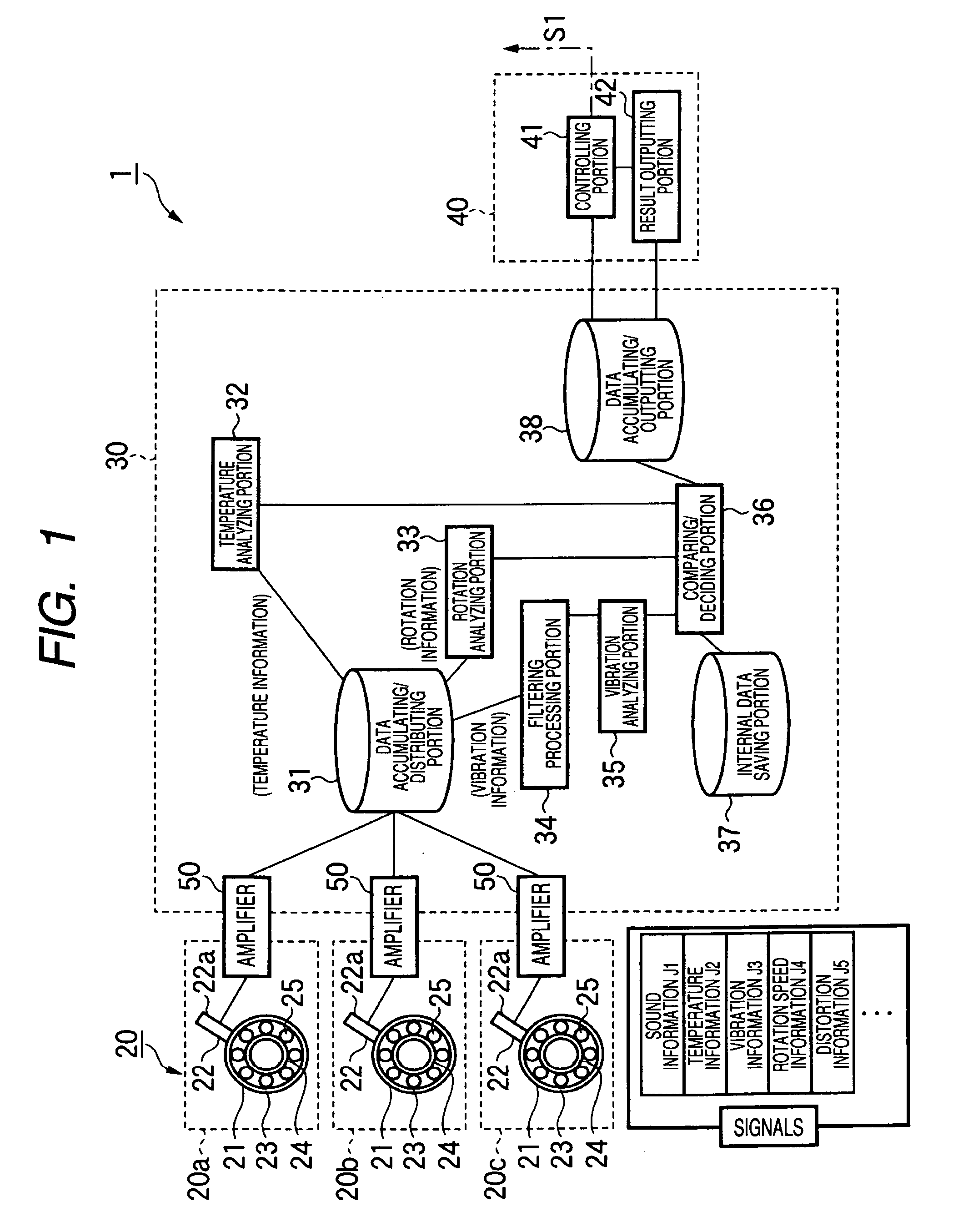
[0183]FIG. 1 shows a railway vehicle abnormality diagnosis system according to the present invention. An abnormality diagnosis system 1 includes a sensing / processing portion 20 having sensor units 22 each provided to each row of a rolling bearing 21 to output a condition of each row as an electric signal, a calculating / processing portion 30 for calculating / processing the electric signals output from the sensor units 22 to decide the condition such as defect, abnormality, or the like of a railway vehicle facility 10, and a controlling / processing portion 40 for controlling and outputting the decided result of the calculating / processing portion 30.

[0184]The abnormality diagnosis system 1 senses the generation of the abnormality due to the wear or the failure of a plurality of rolling bearings 21 in the bearing unit that bears the axle of the railway vehicle. Each rolling bearing 21 has an outer ring 23 as a stationary portion that is fitted into the vehicle body side, an inner ring 24 ...

third embodiment

[0307]Also, like the case of the third embodiment, the calculating / processing portion 73 and the controlling / processing portion 75 provided in the information processing center 71 can be shared with a number of vehicles. Therefore, the abnormality diagnosis system 70 is suited to reduction in the cost of equipment required to execute the abnormality diagnosis.

[0308]Other configurations and operations are similar to those in the first embodiment.

[0309]

[0310]FIG. 30 shows a machinery facility abnormality diagnosis system according to a fifth embodiment of the present invention. In this event, the same reference symbols are affixed to the portions similar to those in the first embodiment, and thus their redundant explanations will be omitted or simplified hereunder.

fifth embodiment

[0311]A machinery facility abnormality diagnosis system 80 in the fifth embodiment detects generation of the abnormality generated due to the wear or the failure of constituent parts of the rolling bearing 21 from the rolling bearing 21 that bears the axle of the railway vehicle. In other words, the rolling bearing 21 that bears the axle corresponds to at least one of the rotating body and the sliding member as the diagnosed object from which the presence or absence of the abnormality is sensed, and the carriage or the railway vehicle whose axle is supported by the rolling bearings 21 corresponds to a machinery facility 90 that contains one or plural rotating bodies or sliding members.

[0312]In the case of the present embodiment, the bearing 21 is the sensor built-in bearing in which the sensor unit 22 for sensing various physical quantities such as sound, vibration, or the like generated in the rotating operation of the bearing and outputting them as the electric signal is fitted in...


PUM


Abstract

An abnormality diagnosis system for diagnosing a presence or absence of an abnormality of a bearing unit for a railway vehicle axle, comprises a sensing / processing portion for outputting a signal generated from the bearing unit as an electric signal, a calculating / processing portion for making an abnormality diagnosis of the bearing unit based on an output of the sensing / processing portion, a result outputting portion for outputting a decision result of the calculating / processing portion, and a controlling / processing portion for feeding back a control signal to a control system of the railway vehicle based on the decision result.

Description

TECHNICAL FIELD [0001]The present invention relates to a machinery facility condition monitoring method and system and an abnormality diagnosis system and, more particularly, a machinery facility condition monitoring method and system and an abnormality diagnosis system capable of monitoring conditions such as an abnormality, and so forth in a machinery facility such as a railway vehicle facility, a machine tool, a windmill, a reduction gear, an electric motor, or the like including at least one of a rotating body and a sliding member such as a rolling bearing, a sliding bearing, a ball screw, a linear guide, a linear ball bearing, and the like without decomposition of the machinery facility.BACKGROUND ART [0002]In the prior art, in order to prevent generation of the failure due to the wear or the failure of the rotating body or the sliding member, a thorough overhaul and a visual inspection are applied periodically to the machinery facility such as the railway vehicle facility, the...

Claims


Application Information

Patent Timeline
Patent Type & Authority Patents(United States)
IPC IPC(8): G06F11/00B61F15/20B61K9/04F16C19/52G01M17/10
CPCB61F15/20B61K9/04F03D11/0008G01M13/045G01M17/10F16C19/52F05B2260/80Y02E10/722G01N2291/02881G01N2291/2696F16C19/386F03D80/70F16C2326/10F16C2360/31Y02E10/72
Inventor MIYASAKA, TAKANORIARAMAKI, HIROTOSHIMUTOU, YASUSHISAHARA, JUNTARO
Owner NSK LTD
Why Eureka
Try Eureka