
Pointing device for digital camera display

a technology of pointing device and digital camera, applied in the field of digital cameras, can solve the problems of difficult use of interface controls, awkward use of location or icon design, and inability to design locations or icons, etc., and achieve the effect of improving the user interface of digital cameras, increasing the ease of use and functionality of digital cameras, and fast, accurately and robustly permitting

Inactive Publication Date: 2007-03-06
SNAPTRACK
View PDF26 Cites 59 Cited by
  • Summary
  • Abstract
  • Description
  • Claims
  • Application Information

AI Technical Summary

Benefits of technology

[0008]A process and apparatus is described to improve a digital camera user interface and increase ease of use and functionality of a digital camera by quickly, accurately and robustly permitting cursor control and designation in a digital camera display.

Problems solved by technology

This arrangement makes the interface controls more difficult to use, because the user will not be able to see the controls while viewing the display.
In the case of the switch, trackball or joystick, it is awkward to designate locations or icons when looking through the camera veiwfinder because the user must hold the camera while manipulating the controls.
This interface is also awkward to use, however, because the motion causes the cursor to wander around the viewing area in an unintuitive way.
Thus, it can be seen that modern user interface techniques impose ease of use and functionality limits upon digital cameras, and hinder the use of these cameras in many applications.

Method used


Image

  • Pointing device for digital camera display
  • Pointing device for digital camera display
  • Pointing device for digital camera display

Examples


Embodiment Construction

[0022]Embodiments of the invention are discussed below with reference to FIGS. 1–10b. Those skilled in the art will readily appreciate that the detailed description given herein with respect to these figures is for explanatory purposes, however, because the invention extends beyond these limited embodiments.

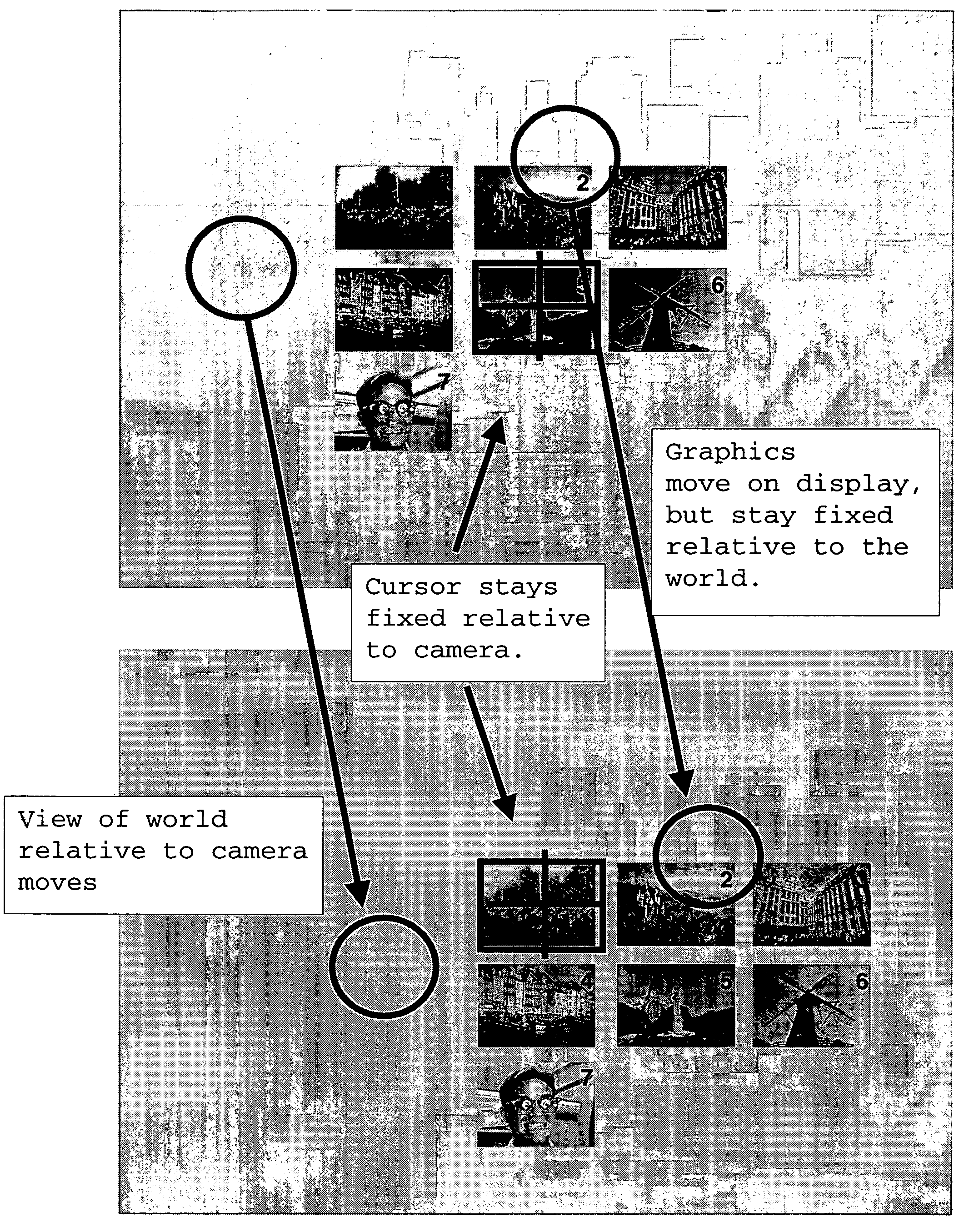
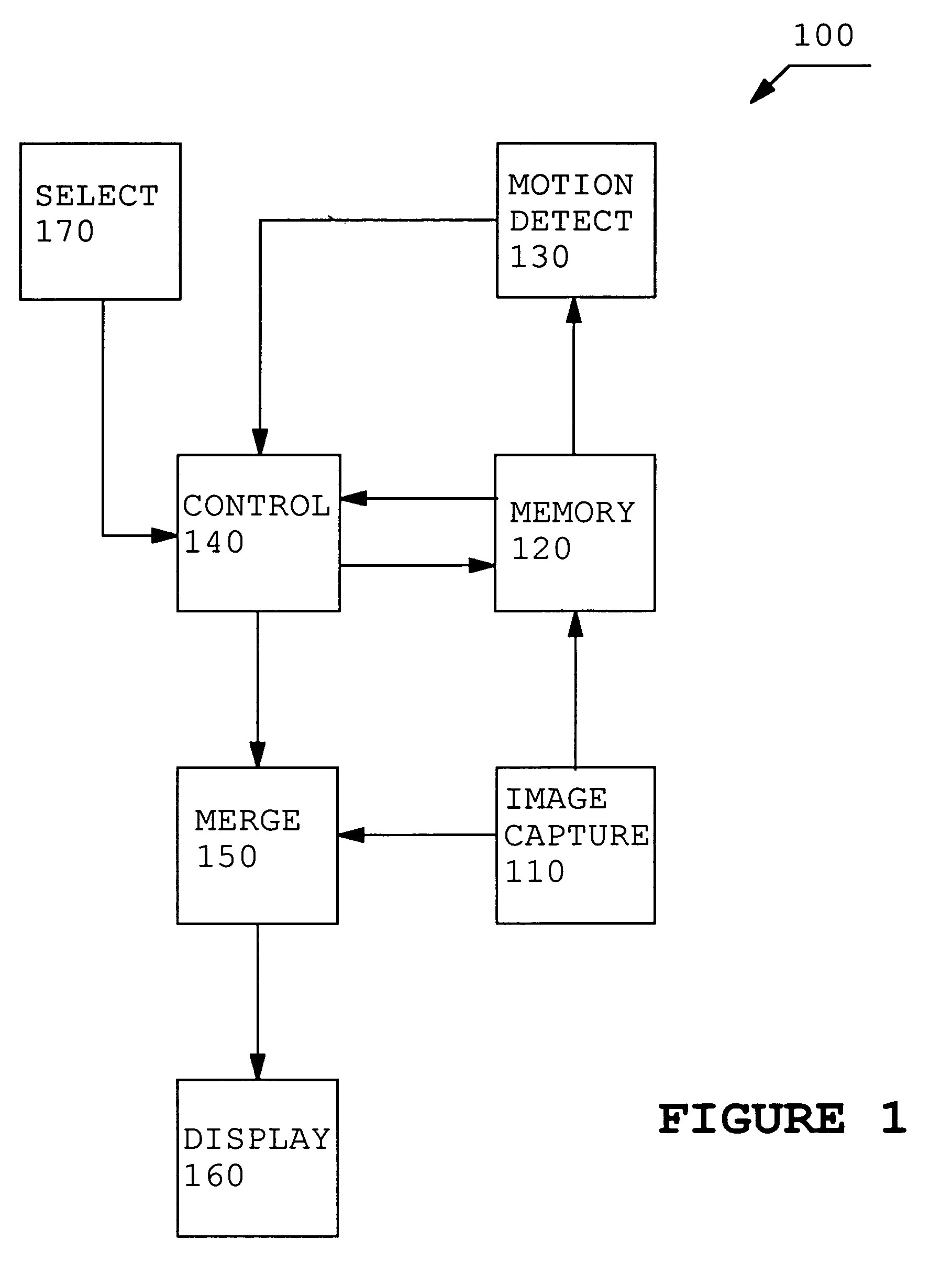
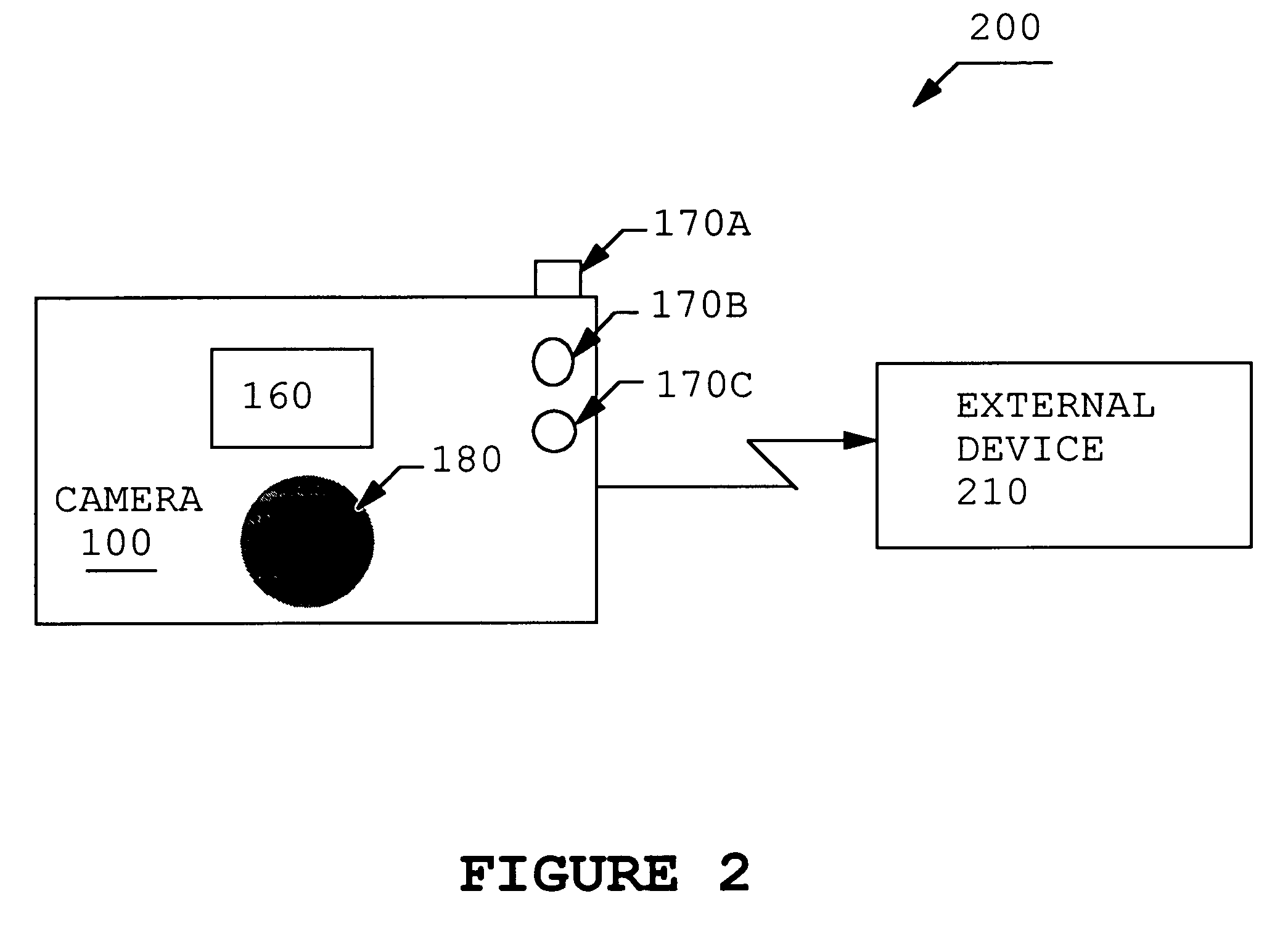
[0023]The invention described here allows a digital camera to be used as a pointing device such as a mouse or trackball. The motion of the camera is detected, and the motion of the camera is used to position graphic elements on the camera's own display. The camera's motion can be detected with sensors, such as gyroscopes, or the camera itself can be used as a motion sensor. One application of this involves using the camera as a computer mouse, or like a gun-sight, to select images from a sheet of low-resolution (“thumbnail”) images. The motion of the camera is tracked, and the user aims at the desired image from a sheet of thumbnail images. This application is illustrated in grea...


PUM


Abstract

A process and apparatus is described to improve a digital camera user interface and increase ease of use and functionality of a digital camera by quickly, accurately and robustly permitting cursor control and designation in a digital camera display. A digital camera is used as a pointing device such as a mouse or trackball. The motion of the camera is detected, and the motion of the camera is used to position graphic elements on the camera's own display. The camera's motion can be detected with sensors, such as gyroscopes, or the camera itself can be used as a motion sensor. One application of this involves using the camera as a computer mouse, or like a gun-sight, to select images from a sheet of low-resolution (“thumbnail”) images. The motion of the camera is tracked, and the user aims at the desired image from a sheet of thumbnail images. The thumbnails appear to be fixed relative to the world because the camera can continuously reposition them in the display based upon the motion of the camera. The user can then select a thumbnail in an intuitive manner by simply pointing the camera at the desired thumbnail. For alternative embodiments, the interface can be used to select regions of greater extent than can be viewed in the viewer or to virtually review images.

Description

BACKGROUND OF THE INVENTION[0001]1. Field of the Invention[0002]The present invention relates to digital cameras and, more particularly, to a pointing device-based graphical user interface that uses the camera display.[0003]2. Description of the Related Art[0004]Digital cameras have not generally used pointing devices to interact with the interface presented on the display. Typically, they use a set of push buttons to step through menus and to select images from memory for display and deletion. New digital cameras may rely on micro display devices, instead of the now more common panel display. To view a micro display, the user needs to hold the display close to his or her eye and view the display through an eyepiece. This arrangement makes the interface controls more difficult to use, because the user will not be able to see the controls while viewing the display.[0005]U.S. Pat. No. 5,808,678, Yuji Sakaegi, entitled “Method and Apparatus for Designing a Position on a View Finder Bas...

Claims


Application Information

Patent Timeline
Patent Type & Authority Patents(United States)
IPC IPC(8): H04N5/222H04N5/228G03B13/04G06F3/038G03B15/00G03B17/00G03B17/20G03B19/02G06F1/16G06F3/033G06F3/0346G06F3/042G06F3/0481G06F3/0487H04N5/232
CPCG06F1/1626G06F1/1686H04N5/23293G06F3/0304G06F2200/1637H04N23/632H04N23/635
Inventor SILVERSTEIN, D. AMNON
Owner SNAPTRACK
Learn More