Apparatus and method for debugging software

Inactive Publication Date: 2007-03-06
CANON KK
View PDF5 Cites 16 Cited by
  • Summary
  • Abstract
  • Description
  • Claims
  • Application Information

AI Technical Summary

Benefits of technology

[0008]It is an object of the present invention to provide a software debugging apparatus and method that can extract information necessary for a software des

Problems solved by technology

That is, usually, in debugging of software, there is a limitation in obtained debug information and it is very difficult to obtain detailed information about hardware in units of a clock signal.
When utilizing dump inf

Method used


Image

  • Apparatus and method for debugging software
  • Apparatus and method for debugging software
  • Apparatus and method for debugging software

Examples


Embodiment Construction

[0017]A preferred embodiment of the present invention will now be described in detail with reference to the drawings.

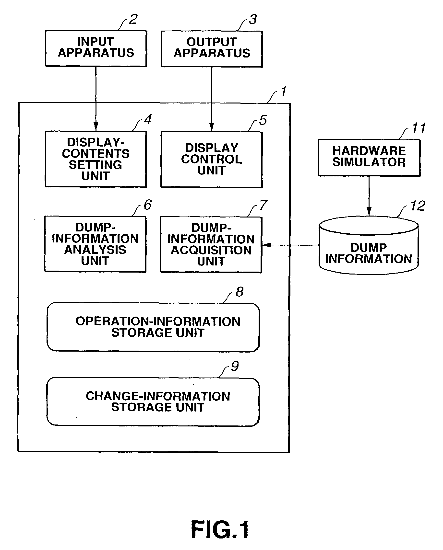
[0018]FIG. 1 is a schematic block diagram illustrating the configuration of a software debugging apparatus 1 according to the embodiment.

[0019]This software debugging apparatus 1 is configured by storing software in a computer, such as a personal computer, a work station or the like. The software debugging apparatus 1 is connected to an input apparatus 2 including a keyboard, a mouse and the like for inputting necessary information, and an output apparatus 3 configured by a display, such as a CRT (cathode-ray tube) or the like, for displaying information.

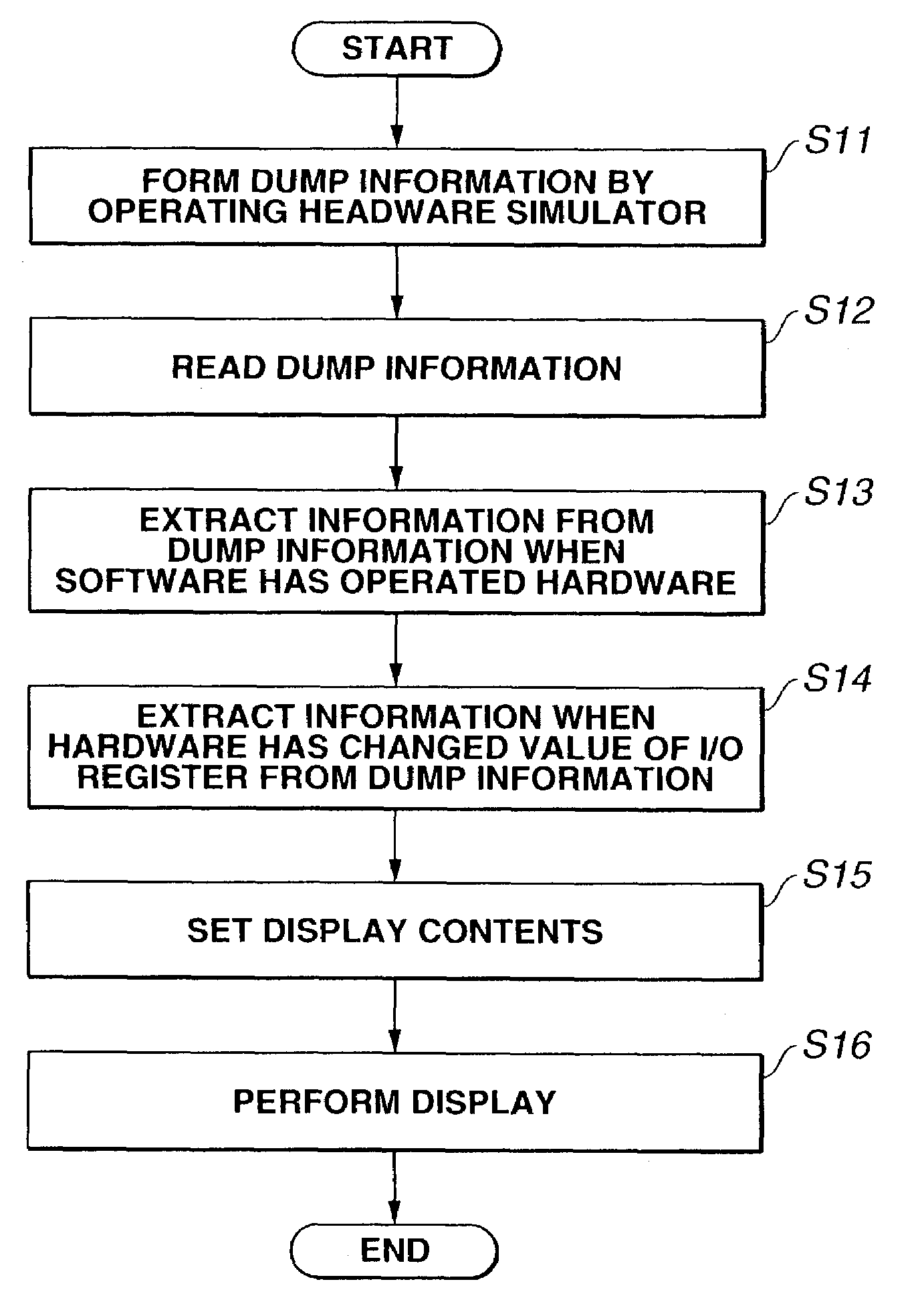
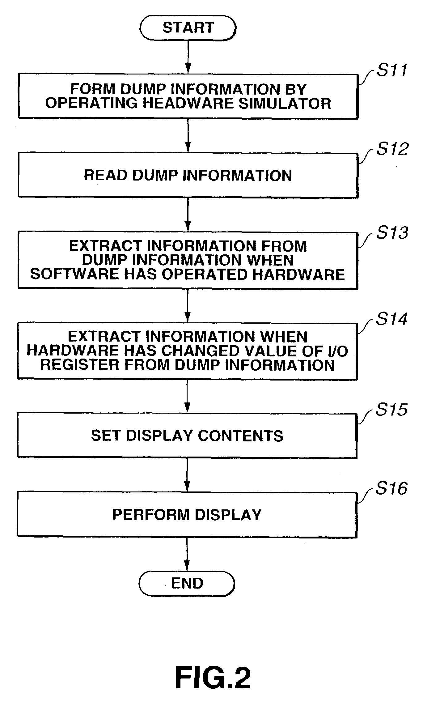
[0020]A hardware simulator 11 performs simulation using a simulation model assuming virtual hardware, described with the HDL, the C language or the like. In this simulation, information relating to the waveform of each signal pin, the value of each internal register, and the like is formed in units of a clock signal o...


PUM


Abstract

In a software debugging apparatus, dump information formed by a hardware simulator is acquired and analyzed. When displaying the result of the analysis, information when software has operated hardware and information when the hardware has changed the value of an I/O register are separately displayed.

Description

BACKGROUND OF THE INVENTION[0001]1. Field of the Invention[0002]The present invention relates to a debugging apparatus and method for debugging software by using a hardware simulator.[0003]2. Description of the Related Art[0004]In recent system LSI (large-scale integrated circuit) development, in order to verify whether or not design is correct before manufacturing hardware, simulation using a simulation model assuming virtual hardware, described with the HDL (Hardware Description Language), the C language or the like. In such simulation, by dumping the waveform of each signal pin, the value of an internal register, and the like in units of a clock signal of hardware, information relating to all signals produced within the hardware can be obtained. The designer of the hardware verifies the designed hardware based on dump information obtained from the hardware simulator.[0005]The dump information is useful for verifying the hardware, and is also very useful for debugging software for...

Claims


Application Information

Patent Timeline
IPC IPC(8): G06F9/44G06F11/00G06F11/28G06F11/32G06F11/36
CPCG06F11/3664G06F11/3636
Inventor ITO, MASAHIRO
Owner CANON KK
Why Eureka
Try Eureka