Self-propelled vehicle for movement within a tubular member

a tubular member and self-propelled technology, applied in the direction of mechanical equipment, instruments, roads, etc., can solve the problems of pipeline failure, pipeline flaws, lost services and revenues, etc., and achieve the effect of compact structure, convenient maneuverability and robust design

Inactive Publication Date: 2007-03-13
ARIZONA PUBLIC SERVICE
View PDF12 Cites 48 Cited by
  • Summary
  • Abstract
  • Description
  • Claims
  • Application Information

AI Technical Summary

Benefits of technology

[0014]Accordingly, it is an advantage of the present invention that a self-propelled vehicle for movement in a tubular member is provided.
[0015]It is another advantage of the present invention that a self-propelled vehicle is provided that imparts sufficient traction force to negotiate steep inclines and vertical pipe sections.
[0016]Another advantage of the present invention is that a self-propelled vehicle is provided that imparts sufficient traction force to enable motive capability in opposition to friction forces caused by an umbilical cable and in the presence of slippery conditions.
[0017]Yet another advantage of the present invention is that a self-propelled vehicle is provided that is self-centering within a tubular member, readily maneuverable, compact, and robust in design.
[0018]The above and other advantages of the present invention are carried out in one form by a self-propelled vehicle for movement within a tubular member. The self-propelled vehicle includes a core element and propulsion mechanisms distributed about a perimeter of the core element. Each of the propulsion mechanisms includes a drive belt having an outer side and an inner side, a drive pulley encompassed by the drive belt for engaging the inner side of the drive belt, and means, encompassed by the drive belt, for providing outwardly-directed force to an underlying portion of the drive belt to press the outer side of the drive belt against an inner wall of the tubular member. A motor arrangement is in communication with each of the propulsion mechanisms for actuating the drive pulley to rotate the drive belt in contact with the inner wall of the tubular member thereby moving the vehicle.

Problems solved by technology

Pipelines can develop flaws over time.
If left uncorrected, such flaws may eventually result in catastrophic failure of the pipeline.
Such a catastrophic failure may result in lost services and revenues, and possible environmental damage.
The mechanics of passing an inspection system through a pipeline present several problems.
For example, a problem that exists in some inspection systems is that they contain components that are unable to negotiate sharp bends or junctions.
These systems are therefore unsuitable for use with convoluted pipelines.
In addition, an inspection system that is unable to negotiate the bends and junctions in a pipeline is likely to become jammed in the pipeline.
If an inspection system becomes stuck within a pipeline, then the system itself becomes a “flaw” (i.e., a blockage) of the pipeline, necessitating repair.
Inspection systems that are propelled by pipeline flow are not always appropriate in particular situations.
For example, pressure or flow propulsion may not be adequate for severely leaking pipes, and cannot be used in empty pipes.
For inspection systems that are pulled through a pipeline by a towline, the towline may produce a significant amount of friction.
For example, it takes considerable force to simply drag a half-inch steel cable through a two-kilometer steel pipeline.
In addition, the cable poses a significant hazard to the pipeline, especially at bends and junctions where the dragging of the cable may actually cut into the inner surface of the pipeline.
Nevertheless, whether it utilizes a manually drawn towline or an umbilical line for power, the range of action of the inspection system is limited because of the friction resistance of the cable to be dragged along on the walls of the pipe.
Unfortunately, the traction of the wheels in any sludge, which may have accumulated at the bottom of the pipe, is sometimes insufficient, thus causing the wheels to slip.
The traction of the wheels has also typically been insufficient in prior art devices when the inspection system is propelled up an incline and / or up a vertical pipe section.
While such continuous treads may impart larger traction forces toward the pipe walls then wheeled units, this prior art pipe crawler has several problems.
As such, the size of the passage between the pair of continuous treads is subject to change, potentially causing damage to cabling passing through the central passage.
In addition, since the same spring force is imposed on both continuous treads of the linked treads, the system is not self-centering within a pipe which could be problematic for attached inspection devices and when negotiating bends or curves in the pipe.
Furthermore, the diametrically opposed pairs of continuous treads cannot move independent from one another in order to accommodate variations in the pipe wall.
Accordingly, when the springs between the diametrically opposed pairs of continuous treads extend or retract in response to pipe diameter, the gears of the orthogonally oriented pairs of continuous treads may become misaligned and bind, potentially causing the vehicle to malfunction.
In addition, this transmission gearing system prevents independent speed control of the continuous treads, thereby yielding restricted maneuverability.

Method used


Image

  • Self-propelled vehicle for movement within a tubular member
  • Self-propelled vehicle for movement within a tubular member
  • Self-propelled vehicle for movement within a tubular member

Examples


Embodiment Construction

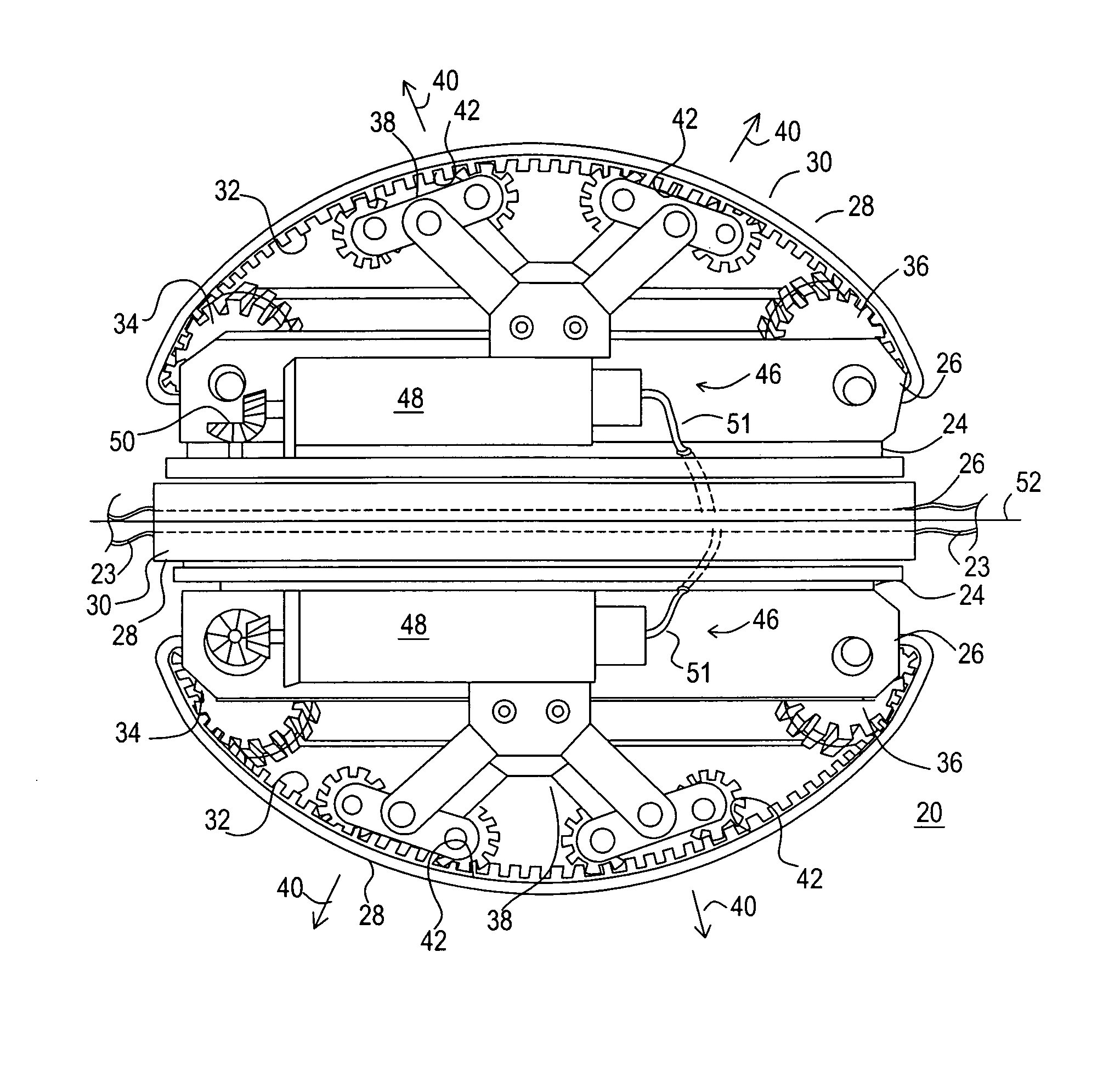
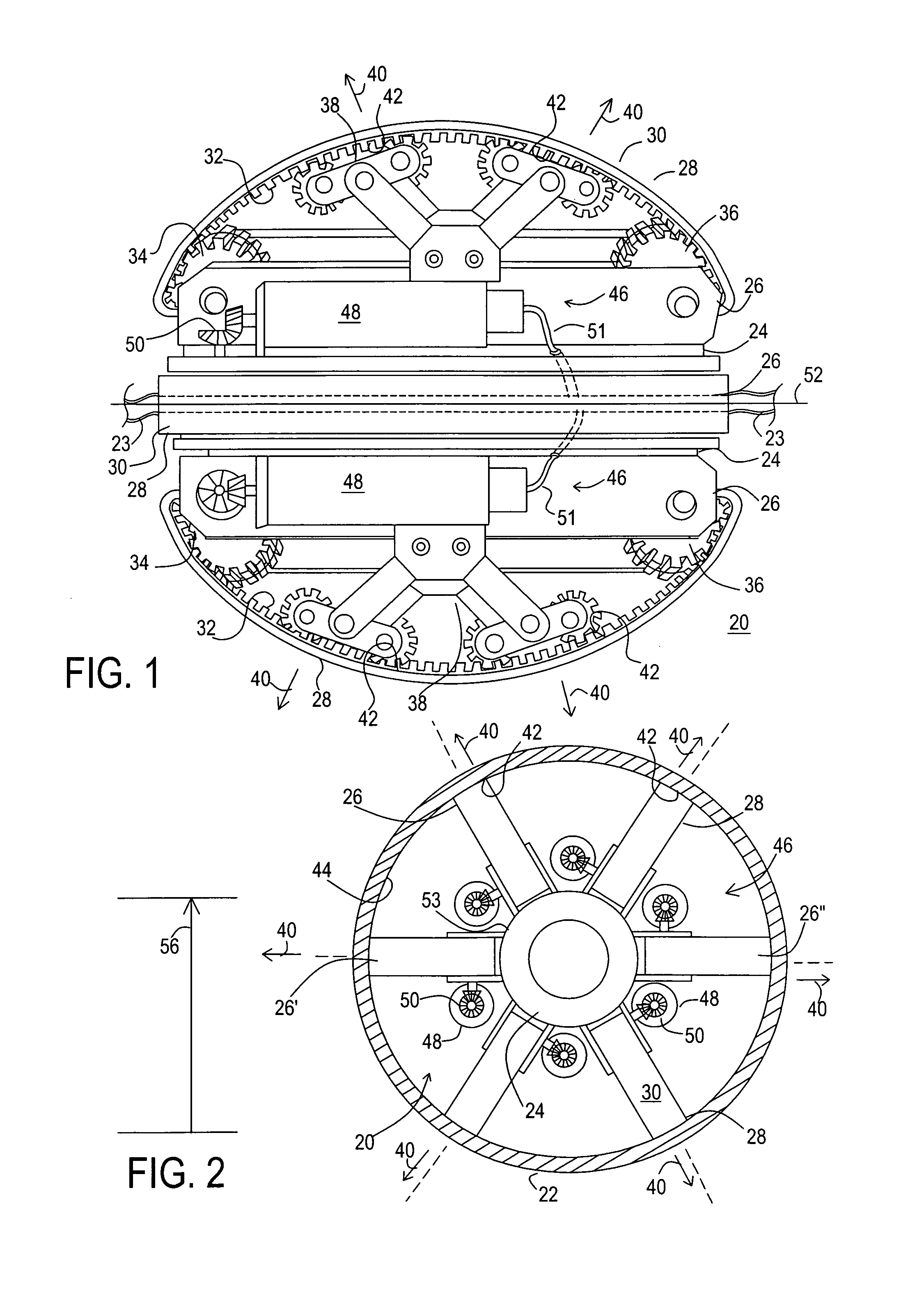
[0039]Referring to FIGS. 1–2, FIG. 1 shows a side view of a self-propelled vehicle 20 in accordance with a preferred embodiment of the present invention, and FIG. 2 shows a schematic end view of self-propelled vehicle 20 within a tubular member 22, such as a pipeline. One or more vehicles 20 may be utilized as part of a pipe inspection system for towing inspection devices, such as transmission and detection units, cameras, sensors, test probes, and the like, through a pipeline system to be inspected. As such, an umbilical line 23 (discussed below) may extend from one or both ends of vehicle 20 for carrying power and / or data.

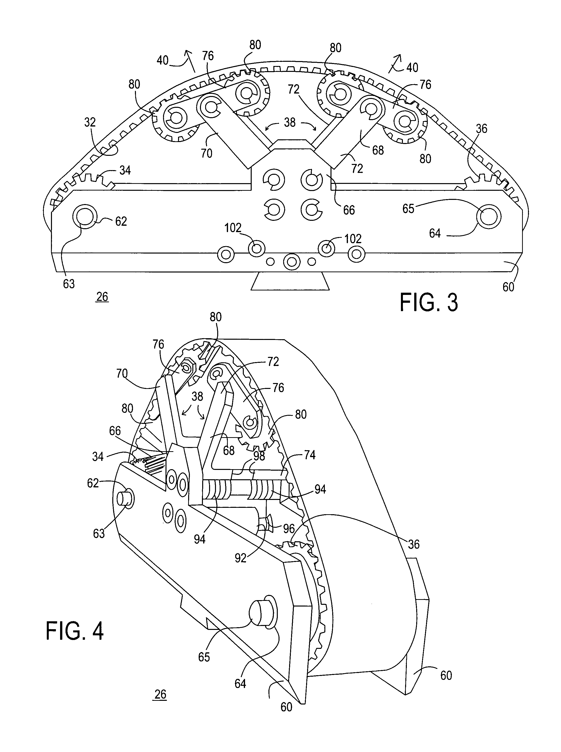
[0040]Self-propelled vehicle 20 includes a core element 24 and propulsion mechanisms 26 distributed about a perimeter of core element 24. Each of propulsion mechanisms 26 includes a drive belt 28 having an outer side 30 and an inner side 32. A first pulley 34 and a second pulley 36 are encompassed, i.e., surrounded, by drive belt 28. More specifically, each of dr...


PUM


Abstract

A self-propelled vehicle (20) for movement within a tubular member (22) includes propulsion mechanisms (28) distributed about a core element (24). Each of the propulsion mechanisms (28) includes a drive belt (28). A first pulley (34), a second pulley (36), and a mid-roller assembly (38) are encompassed by and engage the drive belt (28). The mid-roller assembly (38) is spring-loaded for providing an outwardly-directed force (40) to an underlying portion (42) of the drive belt (28) to press the drive belt (28) against an inner wall (44) of the tubular member (22). A motor arrangement (46), in communication with the propulsion mechanisms (28), actuates one of the first and second pulleys (34, 36) to rotate the drive belt (28) in contact with the inner wall (44) of the tubular member (22) thereby moving the vehicle (20) within the tubular member (22).

Description

TECHNICAL FIELD OF THE INVENTION[0001]The present invention relates to the field of self-propelled vehicles. More specifically, the present invention relates to a self-propelled vehicle adapted to travel through tubular members, such as pipes, and navigate bends and inclines within the tubular members.BACKGROUND OF THE INVENTION[0002]Pipelines can develop flaws over time. If left uncorrected, such flaws may eventually result in catastrophic failure of the pipeline. Such a catastrophic failure may result in lost services and revenues, and possible environmental damage. Because a pipeline may fail without warning, early detection of flaws is fundamental to preventing catastrophic failure.[0003]A wide variety of pipe inspection systems that carry or draw inspection equipment through a pipeline are known. These inspection systems, generally referred to as pipe crawlers, pipe inspection pigs, and the like, are used for inspecting the interior walls of piping systems for damaged or flawed...

Claims


Application Information

Patent Timeline
Patent Type & Authority Patents(United States)
IPC IPC(8): B61B13/10G01M99/00
CPCF16L55/32
Inventor STOUT, JOHN HUGO
Owner ARIZONA PUBLIC SERVICE
Why Eureka
Try Eureka