Bearing system for a turbocharger

a bearing system and turbocharger technology, applied in the field of turbochargers, can solve the problems of inability to provide some inertial damping of vibration, and achieve the effects of reducing friction wear, high durability, and easy assembly

Active Publication Date: 2007-03-13
BORGWARNER INC
View PDF4 Cites 66 Cited by
  • Summary
  • Abstract
  • Description
  • Claims
  • Application Information

AI Technical Summary

Benefits of technology

[0015]Since the bearing spacer has a greater amount of surface area in contact with the bearings, it will rotate at approximately the same speed as the bearings, which is optimal. Since the bearing spacer does not have radial “pilot” protrusions, it will not cause shear of oil, will not introduce drag to impede rotation of the turbocharger. Since the bearing system is not a one-piece system, it will fit to the turbocharger without requiring precise machining. Since the bearing spacer is radially supported by the bearings, vibration can be transmitted from one bearing to the other to a limited extent, thus providing some inertial damping of vibration not possible with a free-floating bearing spacer. Since the three bearing pieces rotate at the same speed, friction wear is reduced. Since the bearing spacer is radially supported, the bearing spacer exhibits resistance to wobble. The invention also provides a bearing system that is simple and relatively inexpensive to manufacture, easy to assemble, and is highly durable.

Problems solved by technology

Since the bearing spacer is radially supported by the bearings, vibration can be transmitted from one bearing to the other to a limited extent, thus providing some inertial damping of vibration not possible with a free-floating bearing spacer.

Method used


Image

  • Bearing system for a turbocharger
  • Bearing system for a turbocharger
  • Bearing system for a turbocharger

Examples


Embodiment Construction

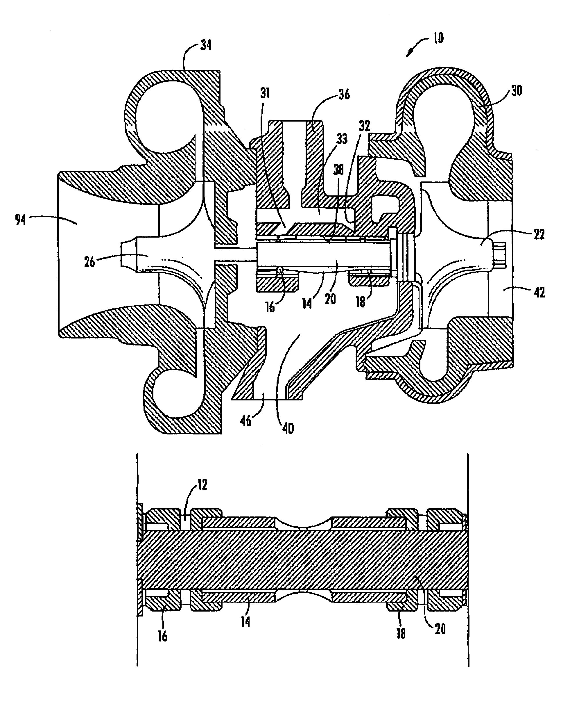
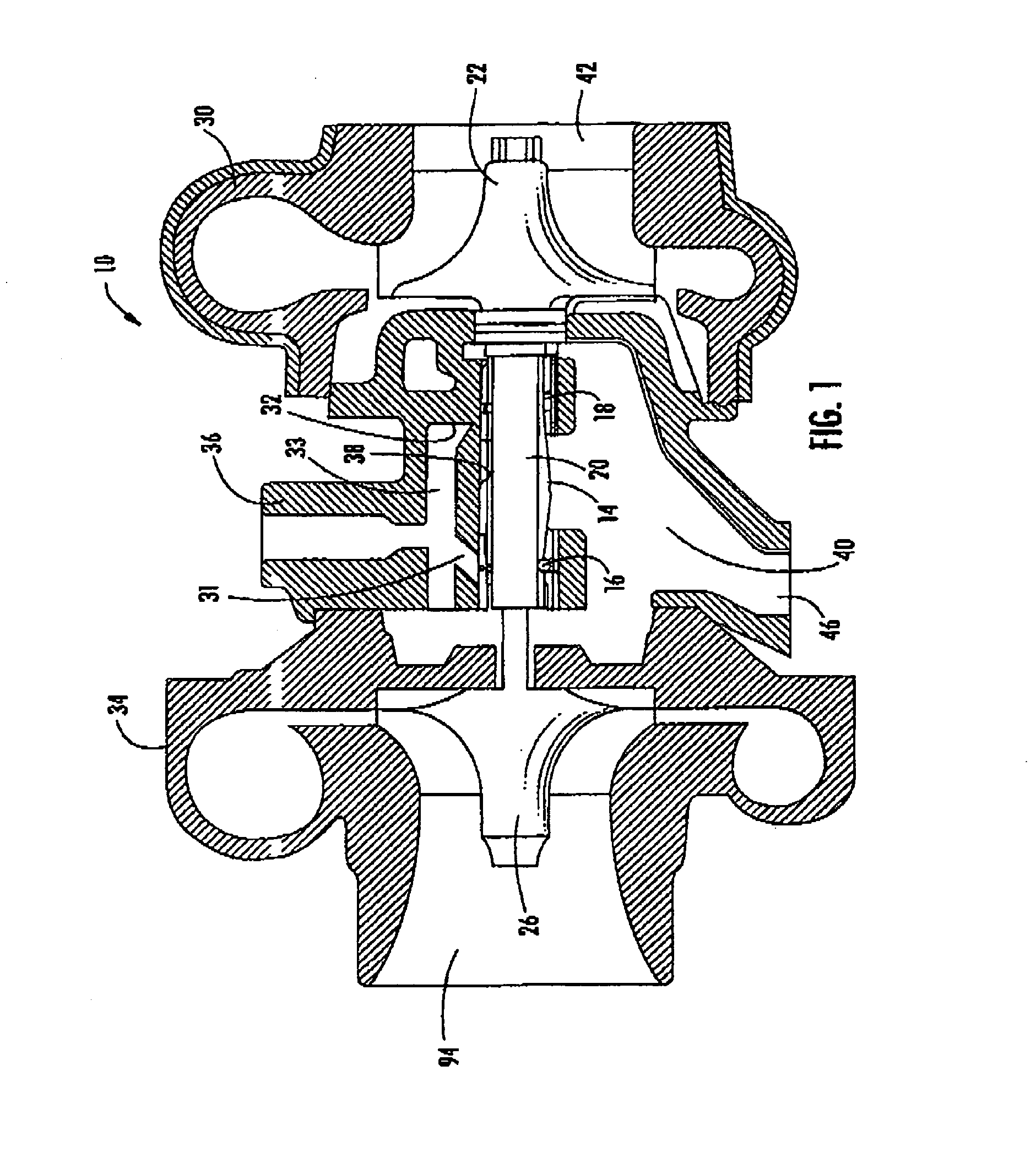
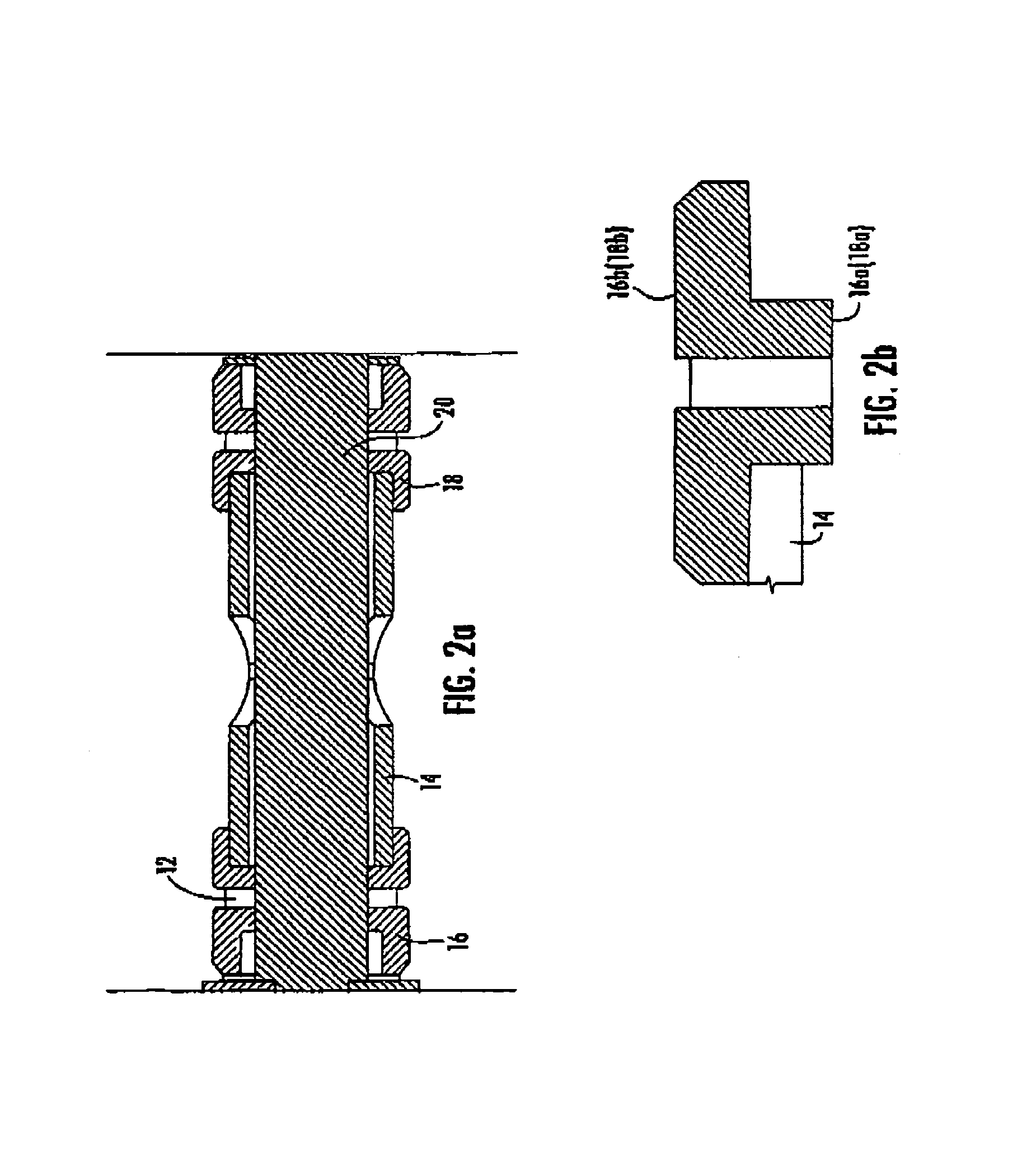
[0020]The illustrative turbocharger 10 depicted in FIG. 1 includes turbine wheel in a turbine housing, a compressor wheel in a compressor housing, a shaft connecting the two wheels, and a bearing system for rotationally and axially supporting the shaft.

[0021]The turbine more specifically comprises a turbine wheel 22 and a turbine housing 30 such that exhaust gas is guided to the turbine wheel 22 by the housing. The inertia and expansion energy in the exhaust gas turns the turbine. Once the gas has passed through the blades of the turbine wheel it leaves the turbine housing 30 via the exhaust outlet area 42. If the engine is in idle mode the wheel will be spinning at a lower speed, and as more gas passes through the turbine housing the turbine wheel will rotate faster.

[0022]The function of the compressor is opposite to that of turbines. The compressor uses the energy, which has been extracted from the exhaust gas in the turbine by slowing and expanding (thereby cooling), in order to ...


PUM


Abstract

A bearing system for a turbocharger, simple in design and easy to manufacture, having desired rotational dynamics of a three piece bearing design, yet having the superior vibration damping characteristics of a one piece bearing design. The inboard end of each journal bearing includes an axial recess for receiving an outboard end of a cylindrical bearing spacer, thereby axially locating the journal bearings as well as axially and radially locating the bearing spacer.

Description

FIELD OF THE INVENTION[0001]The present invention relates to a turbocharger for an internal combustion engine and more particularly to an improved turbocharger journal bearing and bearing spacer system.BACKGROUND OF THE INVENTION[0002]Turbochargers are unique mechanical devices in that they are expected to operate at extremely high RPM under conditions of high temperature and changing load, and yet are expected to provide long trouble-free service.[0003]More specifically, a turbocharger is a type of forced induction system. Engine exhaust gases drive a turbine. The turbine is connected via a shaft to a compressor. Ambient air is compressed by the compressor and is fed into the intake manifold of the engine, allowing the engine to combust more fuel, and thus to produce more power for a given displacement. Considering the volumetric gas intake requirements of an engine operating at peak performance and the comparatively small size of a turbocharger, it can be appreciated that a turboc...

Claims


Application Information

Patent Timeline
Patent Type & Authority Patents(United States)
IPC IPC(8): F16C17/18
CPCF01D25/166F16C17/18F16C2360/24F05D2260/96Y10S384/901F05D2220/40F16C17/02F16C17/26
Inventor WARD, DANIEL N.
Owner BORGWARNER INC
Why Eureka
Try Eureka