Micromechanical sensors and methods of manufacturing same

a micromechanical sensor and manufacturing method technology, applied in the direction of fluid pressure measurement, semiconductor electrostatic transducers, instruments, etc., can solve the problems of low sensor sensitivity, inability to meet the needs of large-scale production of microphones, and complicated electroplating process, etc., to achieve sufficient stability of the counter element or the counter electrode, and the acoustic friction resistance of the slot-formed perforation is considerably smaller. , the effect of reducing the sensitivity

Inactive Publication Date: 2007-03-13
INFINEON TECH AG
View PDF10 Cites 141 Cited by
  • Summary
  • Abstract
  • Description
  • Claims
  • Application Information

AI Technical Summary

Benefits of technology

[0013]It is the object of the present invention to provide a highly sensitive micromechanical sensor which can be manufactured in a flexible way, as well as a method of manufacturing such a sensor.
[0017]The present invention includes a novel perforation having slot-formed holes which are preferably arranged uniformly over the counter element, in the preferred embodiment of a silicon microphone, over the counter electrode. According to the invention, the slots have a width which maximally corresponds to double the spacing defined by the cavity between the membrane and the counter element so that the processing of this perforation can easily be integrated into any overall process. Slots having such a width can be closed easily when manufacturing the inventive sensor by depositing the layer which is etched later for producing the cavity since they grow to be closed from both sides when depositing so that a safe closing of the perforation openings results with the size ratios given.
[0018]Such a maximal width of the slots, preferably together with a limited length of them, also ensures a sufficient stability of the counter element or the counter electrode. In addition, a defined rigidity of the counter element or the counter electrode can be ensured when the slots are formed in at least two different directions. The slots arranged in different directions are thus preferably distributed alternatingly and uniformly over the counter element. According to the invention, the slots or slot groups are arranged in respective rows and columns in the counter element, wherein the rows and columns are offset compared to one another. The acoustic friction resistance of the slot-formed perforation is considerably smaller than in the conventional round or squared holes with an equal effective degree of opening.

Problems solved by technology

This rigidity of the entrapped air lowers the sensitivity of the sensor.
These microphones do not have the advantages of a temperature-stable silicon microphone when produced in large numbers.
The complicated process of electroplating is, however, of disadvantage.
In addition, the calibration of the two wafers is problematic in two-chip microphones.

Method used


Image

  • Micromechanical sensors and methods of manufacturing same
  • Micromechanical sensors and methods of manufacturing same
  • Micromechanical sensors and methods of manufacturing same

Examples


Embodiment Construction

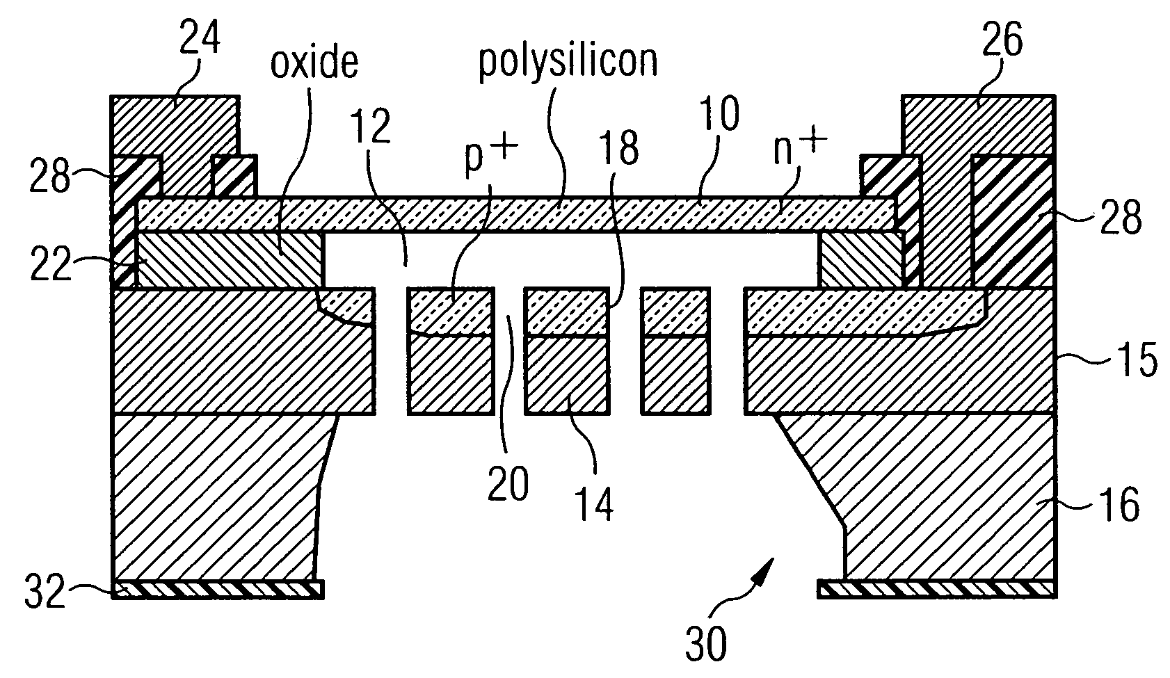
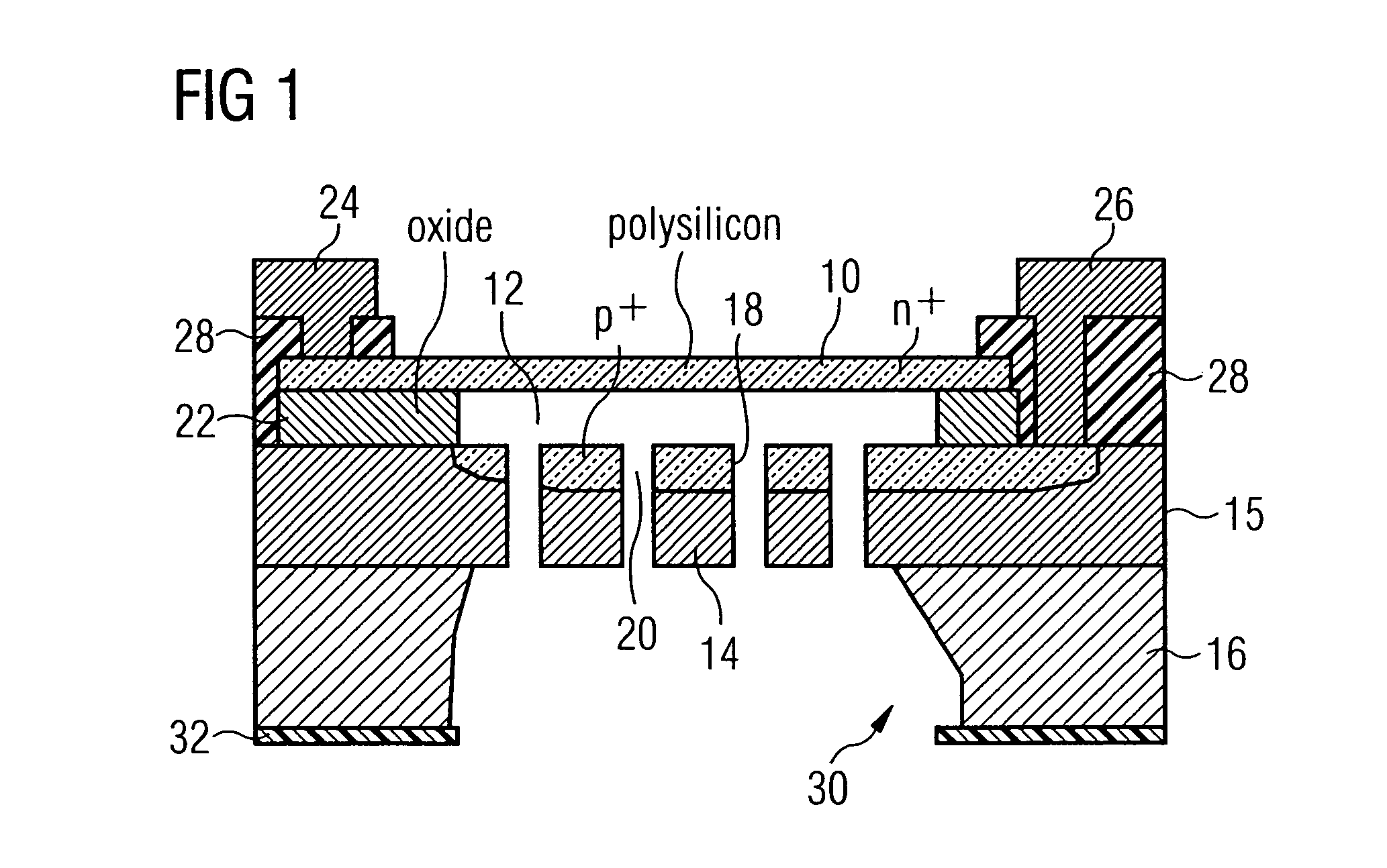
[0026]Referring to FIG. 1, the general setup of an inventive silicon microphone is to be described at first, wherein such a microphone can be manufactured with advantage using the method described in WO 00 / 09440.

[0027]As can be seen from the schematic cross-sectional view of FIG. 1, the one-chip silicon microphone comprises a movable membrane 10 made of an n+-doped polysilicon. The membrane 10, via a sensor cavity 12, is opposite to a counter electrode 14 formed by areas of an epitaxy layer 15 formed on a substrate 16. A p+-doping area 18 and perforation openings 20 are formed in the counter electrode 14.

[0028]The membrane 10 is attached to the counter electrode via a spacing layer 22 which in the embodiment shown consists of oxide. A first terminal electrode 24 is connected to the membrane 10 in an electrically conductive way, while a second terminal electrode 26 is connected to the doping area 18 of the counter electrode 14 in an electrically conductive way. For this purpose, an i...


PUM


Abstract

A micromechanical sensor and, in particular, a silicon microphone, includes a movable membrane and a counter element in which perforation openings are formed, opposite to the movable membrane via a cavity. The perforation openings are formed by slots, the width of which maximally corresponds to double the spacing defined by the cavity between the membrane and the counter element.

Description

CROSS-REFERENCE TO RELATED APPLICATION[0001]This application is a continuation of copending International Application No. PCT / EP02 / 12783, filed Nov. 14, 2002, which designated the United States, and claims priority to German application no. 101 60 830.6 filed on Dec. 11, 2001.FIELD OF THE INVENTION[0002]The present invention relates to micromechanical sensors and methods of manufacturing same and, in particular, to so-called micromechanical one-chip sensors for the manufacture of which a wafer is required.BACKGROUND OF THE INVENTION[0003]In micromechanical sensors, of which a silicon microphone is an example, there are often air-filled cavities having very small dimensions. In a microphone, this is, for example, the air-filled sensor capacity consisting of a sensitive membrane and a rigid counter electrode. Due to the small air volume, the entrapped air applies a strong restoring force on the sensor membrane. This rigidity of the entrapped air lowers the sensitivity of the sensor.[0...

Claims


Application Information

Patent Timeline
Patent Type & Authority Patents(United States)
IPC IPC(8): H01L29/84B81B3/00H04R19/00H04R19/01H04R19/04H04R31/00
CPCB81B3/0021H04R31/00H04R19/005B81B2201/0257H04R19/04B81B2203/0127
Inventor DEHE, ALFONSFUELDNER, MARC
Owner INFINEON TECH AG
Why Eureka
Try Eureka