Stator coil arrangement for an axial airgap electric device including low-loss materials

a technology of axial air gap and stator coil, which is applied in the direction of magnetic circuits characterised by magnetic materials, magnetic circuit shapes/forms/construction, magnetic circuit rotating parts, etc., can solve the problems of low success rate of axial or radial air gap machines, difficult or impossible to directly substitute ordinary steels in conventionally designed motors, and previous attempts at incorporating amorphous materials into conventional radial or axial air gap machines have been largely unsuccessful commercially,

Inactive Publication Date: 2007-03-13
LIGHT ENGINEERING INC
View PDF33 Cites 46 Cited by
  • Summary
  • Abstract
  • Description
  • Claims
  • Application Information

AI Technical Summary

Benefits of technology

[0015]The present invention provides a dynamoelectric electric machine comprising a rotor assembly and a stator assembly that includes a backiron section and a number of stator tooth sections, along with stacked stator phase windings. A slot between each adjacent pair of tooth sections accommodates a plurality of the stacked stator phase windings. Preferably two of such windings are present in each slot. The rotor assembly is supported for rotation about an axis and includes a plurality of poles. The electric device can have any pole and slot count ranging from low to high. The rotor assembly is arranged and disposed for magnetic interaction with the stator assembly. Preferably the stator comprises a generally toroidal structure employing laminated layers composed of at least one low core loss material selected from the group consisting of amorphous and nanocrystalline metals and optimized Fe-based alloy. However, other soft magnetic materials may also be used in constructing all or part of the stator assembly. The use of low core loss, advanced soft magnetic materials affords significant flexibility in design, by making possible a wider range of pole counts and commutating frequencies, while also maintaining high operating efficiency, high power density, and a wide range of possible operating speeds.
[0019]The novel stator coil winding and stacking techniques provided in an aspect of the present invention result in greatly increased stator slot fill, which is a measure of the percentage of stator coil winding in the slot relative to the total volume of the slots. As a result, preferred electric devices of the present invention provide increased performance, power, and efficiency.
[0020]The stator assembly of the present device preferably has a magnetic core made from low loss, high frequency material. More preferably, the stator's magnetic core is made of amorphous metals, nanocrystalline metals, optimized Si—Fe alloys, grain-oriented Fe-based materials or non-grain-oriented Fe-based materials. The introduction of amorphous metals, nanocrystalline metals, optimized Si—Fe alloys, grain-oriented Fe-based materials or non-grain-oriented Fe-based materials into electrical devices enables the device's frequency to be increased above 400 Hz with only a relatively small increase in core loss, as compared to the large increase exhibited in conventional machines, thus yielding a highly efficient electric device capable of providing increased power. The invention further provides a highly efficient electric device with a high pole count capable of providing increased power density and a torque-speed curve extending to higher speed, while retaining improved efficiency,

Problems solved by technology

While it is generally believed that motors and generators having rotors constructed with advanced permanent magnet material and stators having cores made with advanced, low-loss soft materials, such as amorphous metal, have the potential to provide substantially higher efficiencies and power densities compared to conventional radial airgap motors and generators, there has been little success in building such machines of either axial or radial airgap type.
Previous attempts at incorporating amorphous material into conventional radial or axial airgap machines have been largely unsuccessful commercially.
Amorphous metal has unique magnetic and mechanical properties that make it difficult or impossible to directly substitute for ordinary steels in conventionally designed motors.
High speed electric machines are almost always manufactured with low pole counts, lest the magnetic materials in electric machines operating at higher frequencies experience excessive core losses that contribute to inefficient motor design.
It is well known that losses resulting from changing a magnetic field at frequencies greater than about 400 Hz in conventional Si—Fe-based materials causes the material to heat, oftentimes to a point where the device cannot be cooled by any acceptable means.
To date it has proven very difficult to cost effectively provide readily manufacturable electric devices, which take advantage of low-loss materials.
Previous attempts to incorporate low-loss materials into conventional machines generally failed, since the early designs typically relied on merely substituting new soft magnetic materials, such as amorphous metal, for conventional alloys, such as silicon-iron, in machine's magnetic cores.
The resulting electric machines have sometimes provided increased efficiencies with less loss, but they generally suffer from an unacceptable reduction in power output, and significant increases in cost associated with handling and forming the amorphous metal.
As a result, they have not achieved commercial success or market penetration.
A problem that is especially significant in high slot-count devices is the amount of slot space that cannot be filled with windings, because insulation must be interspersed between the stator windings and the stator core.
As a result, the output power and performance of the electric device are also limited.

Method used


Image

  • Stator coil arrangement for an axial airgap electric device including low-loss materials
  • Stator coil arrangement for an axial airgap electric device including low-loss materials
  • Stator coil arrangement for an axial airgap electric device including low-loss materials

Examples


Embodiment Construction

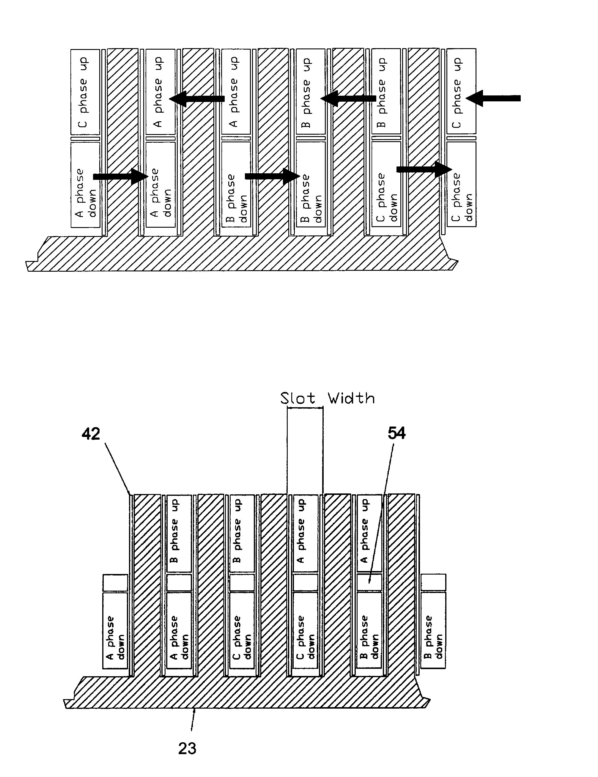
[0036]Preferred embodiments of the present invention will be explained in greater detail hereinafter, with reference to the accompanying drawings. The present invention involves the design and manufacture of an electric device, such as a brushless motor, having a wound stator core made from low-loss material and employing stacked stator windings. Preferably the stator core includes amorphous metals, nanocrystalline metals, optimized Si—Fe alloys, grain-oriented Fe-based materials or non-grain-oriented Fe-based materials.

[0037]General Device Structure

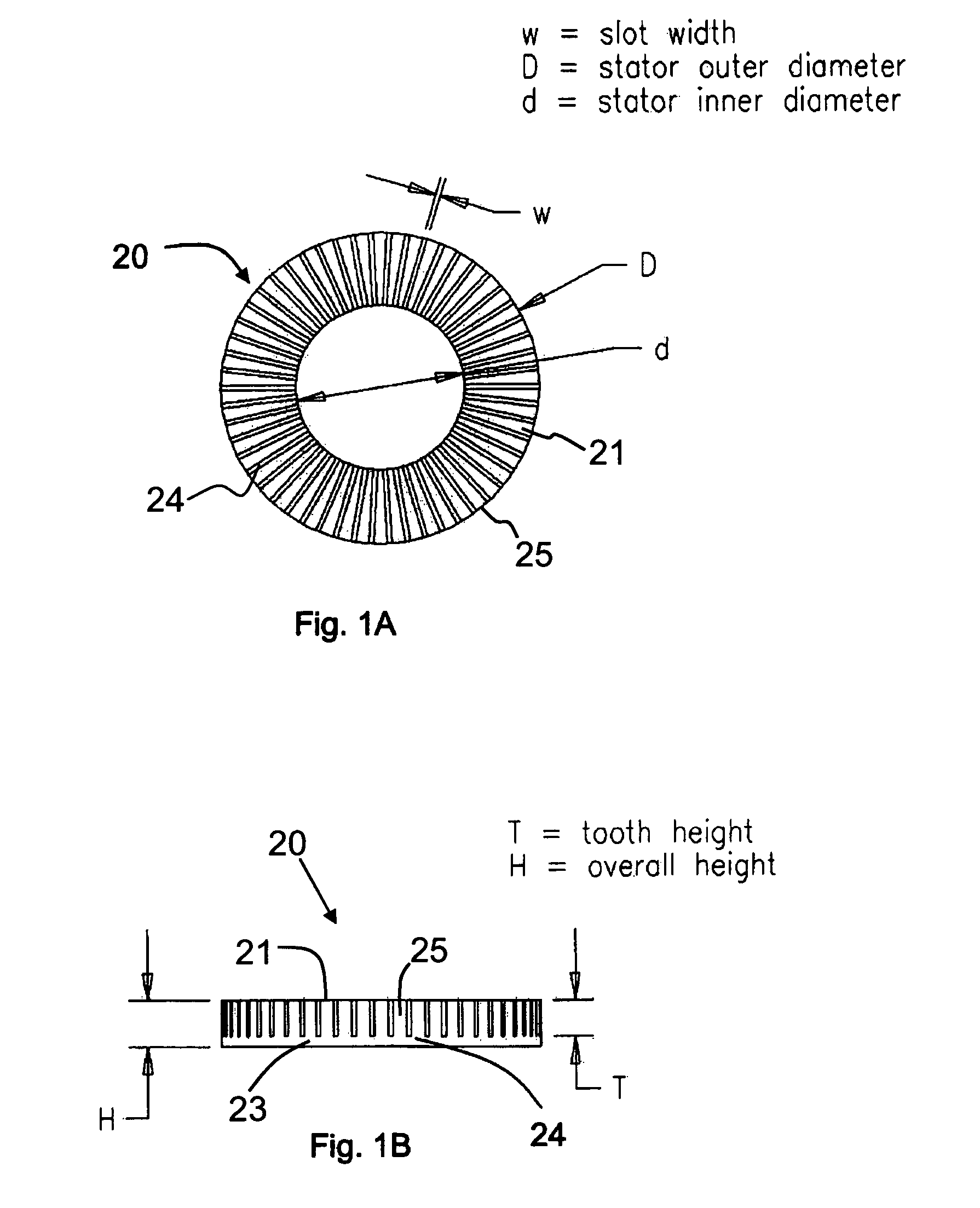
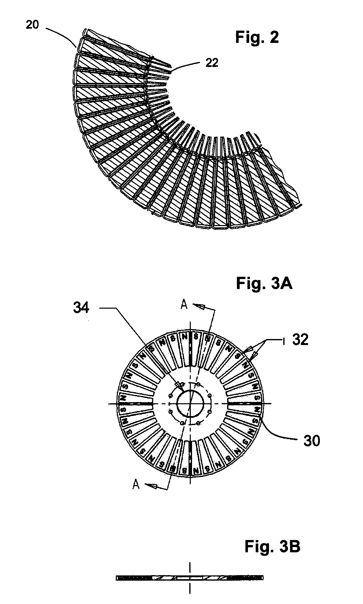
[0038]Commonly assigned U.S. Provisional Application Ser. No. 60 / 444,271 (“the '271 application”) and U.S. patent application Ser. No. 10 / 769,094 (“the '094 application”), which are both incorporated herein in the entirety by reference thereto, provide an electric device having a rotor assembly and a stator arranged in an axial airgap configuration, but with a side-by-side winding configuration. The stator includes a backiron section and...


PUM


Abstract

A dynamoelectric, rotating electric machine includes a stator assembly that includes stacked stator coil windings. The machine is preferably a polyphase, axial airgap device. Improved slot filling results from the stacked stator coil configuration. Device performance capability is thereby increased. The stator assembly of the electric device has a magnetic core made from low loss, high frequency material. A high pole count permits the electrical device to operate at high commutating frequencies, with high efficiency, high power density and improved performance characteristics. Low-loss materials incorporated by the device include amorphous metals, nanocrystalline metals, optimized Si—Fe alloys, grain-oriented Fe-based materials or non-grain-oriented Fe-based materials.

Description

RELATED U.S. APPLICATION DATA[0001]This application claims the benefit of co-pending U.S. Provisional Patent Application Ser. No. 60 / 516,789, filed Nov. 3, 2003, and entitled “Stator Coil Arrangement For An Axial Airgap Electric Device Including Low-Loss Materials,” which is incorporated herein in the entirety by reference thereto.BACKGROUND OF THE INVENTION[0002]1. Field of the Invention[0003]The invention relates to a dynamoelectric, rotating machine; and more particularly, to an axial airgap, dynamoelectric, rotating machine comprising a rotor assembly and a stator assembly that includes a stacked stator coil arrangement.[0004]2. Description of the Prior Art[0005]The electric motor and generator industry is continuously searching for ways to provide dynamoelectric, rotating machines with increased efficiencies and power densities. As used herein, the term “motor” refers to all classes of motoring and generating machines which convert electrical energy to rotational motion and vic...

Claims


Application Information

Patent Timeline
Patent Type & Authority Patents(United States)
IPC IPC(8): H02K1/02H02K3/04H02K3/28H02K21/00H02KH02K19/00
CPCH02K3/12H02K21/24H02K3/28H02K3/18H02K1/02B82Y40/00H02K3/00
Inventor HIRZEL, ANDREW D.
Owner LIGHT ENGINEERING INC
Why Eureka
Try Eureka