Tunable superconducting resonator and methods of tuning thereof

a superconducting resonator and resonator technology, applied in the direction of superconducting magnets/coils, instruments, magnetic bodies, etc., can solve the problems of limiting the application of typical resonant circuits, requiring the use of liquid helium and expensive cooling equipment, and requiring liquid helium for known superconducting materials,

Inactive Publication Date: 2007-03-13
SUPERCONDUCTOR TECHNOLOGIES INC
View PDF30 Cites 11 Cited by
  • Summary
  • Abstract
  • Description
  • Claims
  • Application Information

AI Technical Summary

Benefits of technology

[0014]In one embodiment, a superconducting capacitor is fabricated monolithically on the same substrate as is an inductor. The circuit may be completed by connecting gold contact pads. The capacitance can be easily set by scribing away part of the capacitor and can be easily tuned by placing a dielectric or conductor on top of the capacitor. This embodiment may also include an additional superconducting capacitor as a tuning capacitor which can be used to tune the original capacitor either by scribing the tuning capacitor or by positioning a dielectric or conductor on top of it. Optionally, the signal may be coupled out of the resonant circuit using a superconducting inductor.
[0026]It is still an additional object of this invention to provide coupled superconducting inductor coils for improved reception of electronic signals and for low-loss tuning of resonant circuits.
[0028]It is also another object of this invention to provide photoconductive switches to provide low-loss switching in resonant circuits.

Problems solved by technology

Until recently, attaining the Tc of known superconducting materials required the use of liquid helium and expensive cooling equipment.
Typical resonant circuits are generally limited in their application due to their signal-to-noise ratios (“SNR”).
For example, the SNR in a pickup coil of a MRI detector is a limiting factor for low-field MRI systems.
Although the low-field MRI systems have a number of advantages over high-field MRI (including cost, site requirements, patient comfort and tissue contrast), they have not yet found wide-spread use in the U.S. because, in part, of their lower SNR.

Method used


Image

  • Tunable superconducting resonator and methods of tuning thereof
  • Tunable superconducting resonator and methods of tuning thereof
  • Tunable superconducting resonator and methods of tuning thereof

Examples


Embodiment Construction

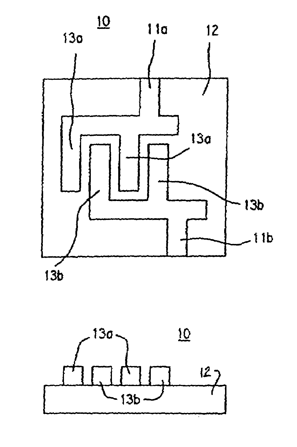
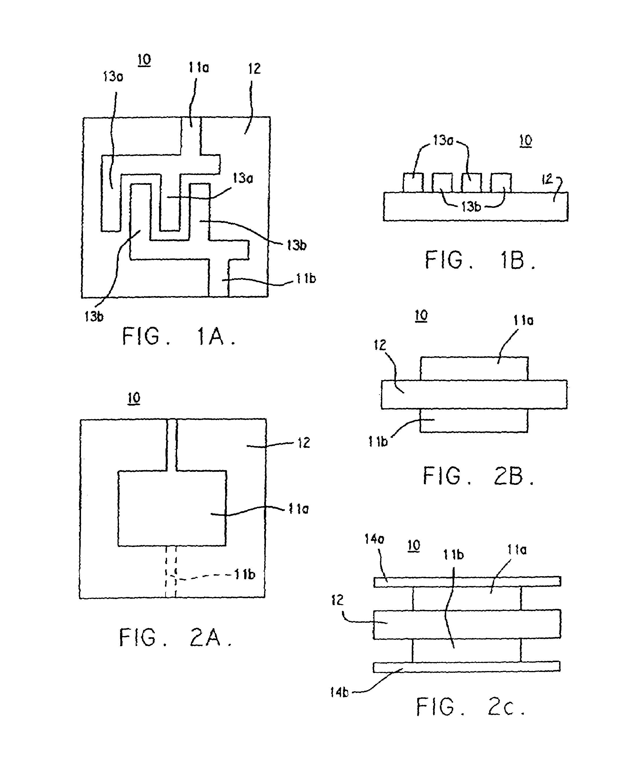
[0047]Turning to the drawings in more detail, FIGS. 1A and 1B and FIGS. 2A, 2B and 2C show respectively an interdigitated structure and a plate structure of superconducting capacitor 10 of the present invention. As shown, the capacitor 10 comprises two superconducting members 11a and 11b separated by a low loss dielectric 12 (e.g. LaAlO3, MgO, sapphire, or polyimide).

[0048]The interdigitated structure shown in FIGS. 1A and 1B comprises a capacitor 10 having superconducting members 11a and 11b fabricated monolithically on one side of the same substrate 12. The members 11a and 11b each comprise a plurality of fingers 13a and 13b respectively which extend on the surface of the dielectric substrate 12. The fingers 13a and 13b are positioned on the dielectric 12 such that fingers 13a are interspersed between fingers 13b.

[0049]The interdigital superconducting capacitor 10 has the benefit of being easily tuned. It can be tuned either by scribing away part of a superconducting member 11a o...


PUM

PropertyMeasurementUnit
diameteraaaaaaaaaa
Tcaaaaaaaaaa
boiling pointaaaaaaaaaa

Abstract

A method of tuning a high temperature superconductor (HTS) resonator includes the steps of providing a HTS inductor and a HTS capacitor, the HTS capacitor being electrically connected to the HTS inductor. A tuning body is provided adjacent to the HTS inductor and the HTS capacitor. The relative position of the tuning body with respect to the HTS inductor and the HTS capacitor is altered so as to tune the resonator. A tunable resonant circuit is provided that includes a substrate having a planar surface. At least one resonator formed from HTS material is disposed on the substrate, the resonator having one or more turns that when combined, turn through greater than 360°.

Description

RELATED APPLICATIONS[0001]This application is a continuation of U.S. application Ser. No. 10 / 393,089, filed Mar. 19, 2003, now U.S. Pat. No. 6,727,702 now allowed, which is a continuation of U.S. application Ser. No. 09 / 970,842, filed on Oct. 3, 2001, now issued as U.S. Pat. No. 6,538,445, which itself is a continuation of U.S. application Ser. No. 07 / 934,921, filed on Aug. 25, 1992, now issued as U.S. Pat. No. 6,335,622, which itself is a continuation-in-part of U.S. application Ser. No. 07 / 719,736, filed on Jun. 24, 1991, now issued as U.S. Pat. No. 5,328,893. The above-identified applications and issued patents are incorporated by reference as if set forth fully herein.FIELD OF THE INVENTION[0002]This invention relates to useful devices from high temperature superconducting materials. Specifically, it relates to circuits having superconducting capacitors and inductors, alone or in combination with other elements made from high temperature superconducting films and, optionally, in...

Claims


Application Information

Patent Timeline
Patent Type & Authority Patents(United States)
IPC IPC(8): G01V3/00G01R33/34H01F6/06H01G4/008H01L39/16H01P1/203H01P7/08H01Q1/36H03K17/00H03K17/78H03K17/92
CPCG01R33/34053G01R33/341G01R33/3671H01F6/06H01G4/008H01P1/203H01P7/08H01P7/088H01Q1/364H03K17/78H03K17/92G01R33/34023G01R33/34007H03K2217/0036G01R33/3642
Inventor HAMMOND, ROBERT BSUN, JONATHAN Z.SCALAPINO, DOUGLAS J.JAMES, TIMOTHY W.BOURNE, LINCOLN C.
Owner SUPERCONDUCTOR TECHNOLOGIES INC
Why Eureka
Try Eureka