Device and method for voltage regulator with stable and fast response and low standby current

a voltage regulator and stable technology, applied in the field of integrated circuits, can solve the problems of reducing reducing the operation time of battery-powered devices, and consuming important current of the voltage regulator in the standby mode, so as to improve the stability of the loop, shorten the response time of the amplifier feedback loop, and reduce the power consumption of the voltage regulator.

Active Publication Date: 2007-03-13
SEMICON MFG INT (SHANGHAI) CORP
View PDF6 Cites 5 Cited by
  • Summary
  • Abstract
  • Description
  • Claims
  • Application Information

AI Technical Summary

Benefits of technology

[0018]Many benefits are achieved by way of the present invention over conventional techniques. Certain embodiments of the present invention provide a large biasing current in the active mode and a small biasing current in the standby mode for the first stage of the operational amplifier. The large biasing current shortens the response time of the amplifier feedback loop in the active mode. The small biasing current lowers the power consumption of the voltage regulator and improves loop stability in the standby mode. Some embodiments of the present invention provides a compensation system. The compensation system has an RC constant in the active mode lower than that in the standby mode. The low RC constant in the active mode substantially cancels the zero resulting from the low impedance of the output transistor at high output current. The high RC constant in the standby mode substantially cancels the zero resulting from the high impedance of the output transistor at low output current. The loop stability of the operational amplifier are improved in both the standby mode and the active mode. Certain embodiments of the present invention provide a delay to the sensing current proportional to the output current. The sensing current is mirrored to provide biasing currents to the output transistor and the differential pair of the first stage of the operational amplifier. The delay system and the current mirror can suppress the overshoot when the output current suddenly drops. For example, the output current drops from the milli-ampere level in the active mode to the micro-ampere level in the standby mode. After this sudden drop, the delayed biasing current facilitates the feedback loop of the operational amplifier to quickly reach a new equilibrium. Some embodiments of the present invention provide a low load current and a low standby current consumed by the voltage regulator in the standby mode. For example, the load current is 1 μA, and the standby current around 1 μA. These embodiments also provide high stability and fast response to the load current change. Depending upon the embodiment, one or more of these benefits may be achieved. These and other benefits will be described in more throughout the present specification and more particularly below.

Problems solved by technology

The current of the voltage regulator in the standby mode consumes important energy.
The energy consumption in the standby mode limits the operation time of battery-powered devices.
Further, some battery-powered devices require low standby power consumption and hence cannot rely on the power regulator.
Consequently, these battery-powered devices usually cannot take advantage of the shrinking transistor size.

Method used


Image

  • Device and method for voltage regulator with stable and fast response and low standby current
  • Device and method for voltage regulator with stable and fast response and low standby current
  • Device and method for voltage regulator with stable and fast response and low standby current

Examples


Embodiment Construction

[0023]The present invention is directed to integrated circuits. More particularly, the invention provides a device and method for stable voltage regulator with fast response. Merely by way of example, the invention has been applied to a battery powered system. But it would be recognized that the invention has a much broader range of applicability.

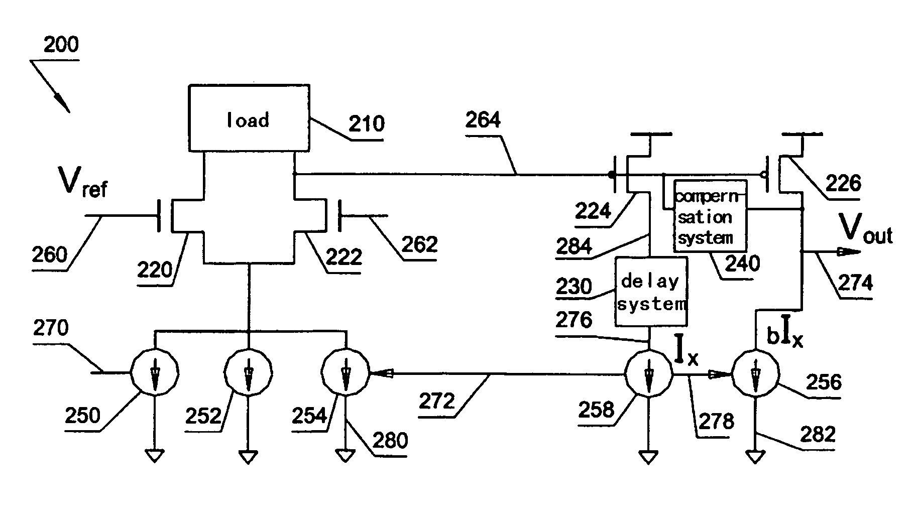
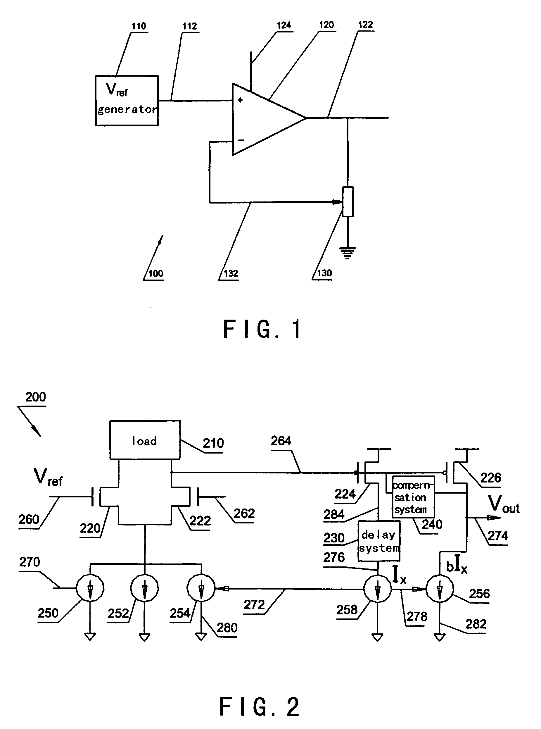
[0024]FIG. 2 is a simplified operational amplifier for voltage regulator according to an embodiment of the present invention. This diagram is merely an example, which should not unduly limit the scope of the claims herein. The device 200 includes the following components:[0025]1. Load 210;[0026]2. Transistors 220, 222, 224 and 226;[0027]3. Delay system 230;[0028]4. Compensation system 240;[0029]5. Current supplies 250 and 252;[0030]6. Current mirror including current mirror components 258, 256 and 254.

[0031]The above electronic devices provide components for an operational amplifier of a voltage regulator according to an embodiment of the p...


PUM


Abstract

An apparatus and method for regulating voltage levels. The apparatus includes a first transistor and a second transistor. The first transistor and the second transistor are each coupled to a first current source and a second current source. Additionally, the apparatus includes a third transistor coupled to the second transistor and configured to receive a first voltage from the second transistor, and a fourth transistor configured to receive the first voltage from the second transistor and generate an output voltage. Moreover, the apparatus includes an adaptive system coupled to the fourth transistor. Also, the apparatus includes a delay system coupled to the third transistor and configured to receive a sensing current from the third transistor and generate a delayed current associated with a predetermined time delay. Additionally, the apparatus includes a current generation system.

Description

CROSS-REFERENCES TO RELATED APPLICATIONS[0001]This application claims priority to Chinese Patent Application No. 200410066517.7, filed Sep. 16, 2004, commonly assigned and incorporated by reference herein for all purposes.[0002]The following three commonly-owned co-pending applications, including this one, are being filed concurrently and the other two are hereby incorporated by reference in their entirety for all purposes:[0003]1. U.S. patent application Ser. No. 11 / 061,062, in the name of Wenzhe Luo, titled, “Device and Method for Voltage Regulator with Low Standby Current,”;[0004]2. U.S. patent application Ser. No. 11 / 060,922, in the name of Wenzhe Luo, titled, “Device and Method for Voltage Regulator with Stable and Fast Response and Low Standby Current,”; and[0005]3. U.S. patent application Ser. No. 11 / 061,197, in the name of Wenzhe Luo and Paul Ouyang, titled, “Device and Method for Low-Power Fast-Response Voltage Regulator with Improved Power Supply Range,”.STATEMENT AS TO RI...

Claims


Application Information

Patent Timeline
Patent Type & Authority Patents(United States)
IPC IPC(8): H03K17/16
CPCG05F1/565
Inventor LUO, WENZHE
Owner SEMICON MFG INT (SHANGHAI) CORP
Why Eureka
Try Eureka