Optical element having a plurality of ring-shaped zones
- Summary
- Abstract
- Description
- Claims
- Application Information
AI Technical Summary
Benefits of technology
Problems solved by technology
Method used
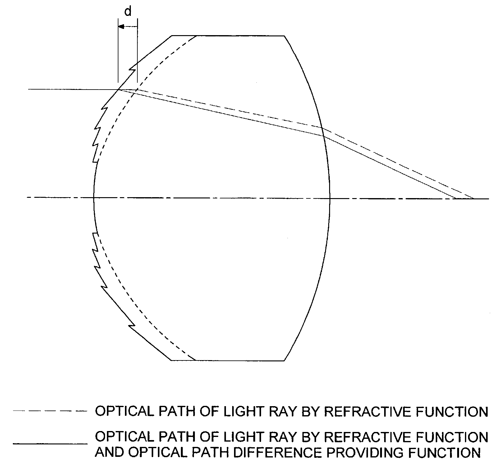
Image

Examples
first embodiment
(First Embodiment)
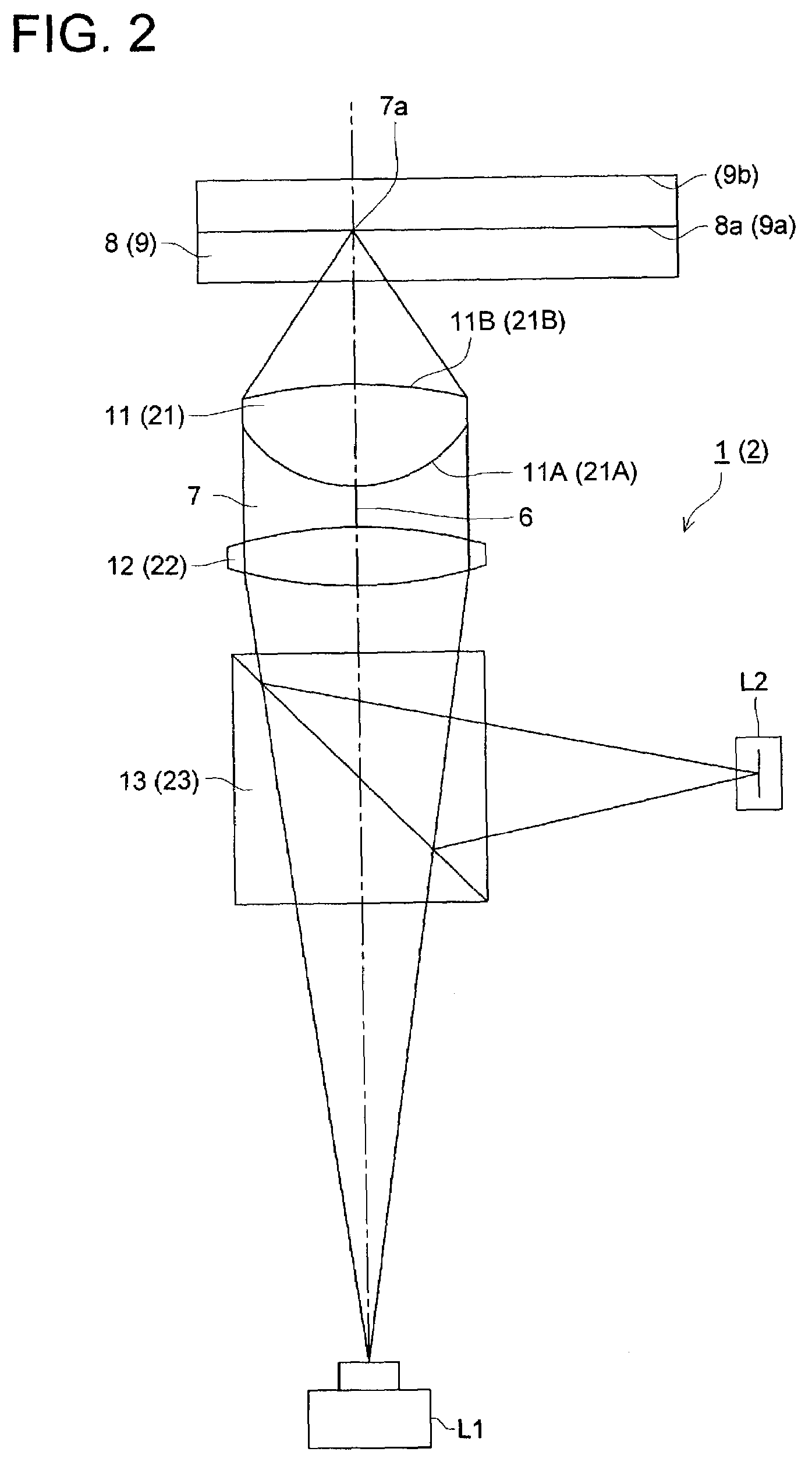
[0117]Optical pickup device 1 of the present embodiment is one designed to conduct reading and writing of MO, and operating reference wavelength λ0=685 nm, numerical aperture of optical system NA=0.55 and focal length=2.7 mm are used for the design.
[0118]Shapes of the diffractive surfaces (first surface 11A, second surface 11B) and refractive indexes of the multi-ring-shaped zone phase difference lens 11 used in the optical pickup device 1 are established as follows.
[0119]Lens data of the multi-ring-shaped zone phase difference lens 11 are shown in Table 1
[0120]
TABLE 1DistanceonSur-Radius ofopticalfacecurvatureaxis dRefractive index nNo.R (mm)(mm)λ = 675 nmλ = 685 nmλ = 695 nm0∞11.8622.151.53681.53641.53622−3.8750.853∞0.61.581.581.584∞
[0121]In Table 1 the surface numbers 1 and 2 are respectively the first surface 11A and second surface 11B of the multi-ring-shaped zone phase difference lens 11. The surface No. 3 and 4 are respectively the disk surface of MO and a r...
second embodiment
(Second Embodiment)
[0134]Optical pickup device 2 in the present embodiment is one designed to conduct reading and writing for HD-DVD, and it is designed under the conditions that the operating reference wavelength λ0 is 405 nm, numerical aperture NA of an optical system is 0.85 and a focal length is 1.76 mm.
[0135]Shapes of the diffractive surfaces (first surface 21A, second surface 21B) and refractive indexes of the multi-ring-shaped zone phase difference lens 21 used in the optical pickup device 2 are established as follows.
[0136]Lens data of the multi-ring-shaped zone phase difference lens 21 are shown in Table 4.
[0137]
TABLE 4Distance onRadius ofopticalcurvatureaxis dRefractive index nSurface No.R (mm)(mm)λ = 395 nmλ = 405 nmλ = 415 nmSubject∞1 (Aspheric1.1702.651.52651.52491.5235surface)2 (Aspheric−0.9750.34surface)3 Cover∞0.11.621.621.62glass4∞
[0138]In Table 4 the surface numbers 1 and 2 are respectively the first surface 21A and second surface 21B of the multi-ring-shaped zone ...
PUM
 Abstract
Description
Claims
Application Information
 - R&D Engineer
- R&D Manager
- IP Professional
- Industry Leading Data Capabilities
- Powerful AI technology
- Patent DNA Extraction
Browse by: Latest US Patents, China's latest patents, Technical Efficacy Thesaurus, Application Domain, Technology Topic.
© 2024 PatSnap. All rights reserved.Legal|Privacy policy|Modern Slavery Act Transparency Statement|Sitemap