Flexible application of mapping algorithms within a packet distributor

a technology of packet distributor and mapping algorithm, applied in the field of packet-based communication systems, can solve the problems of not working as well in an environment, and not offering the flexibility to apply different mapping algorithms to different types of packets

Active Publication Date: 2007-03-13
LUCENT TECH INC
View PDF11 Cites 37 Cited by
  • Summary
  • Abstract
  • Description
  • Claims
  • Application Information

AI Technical Summary

Benefits of technology

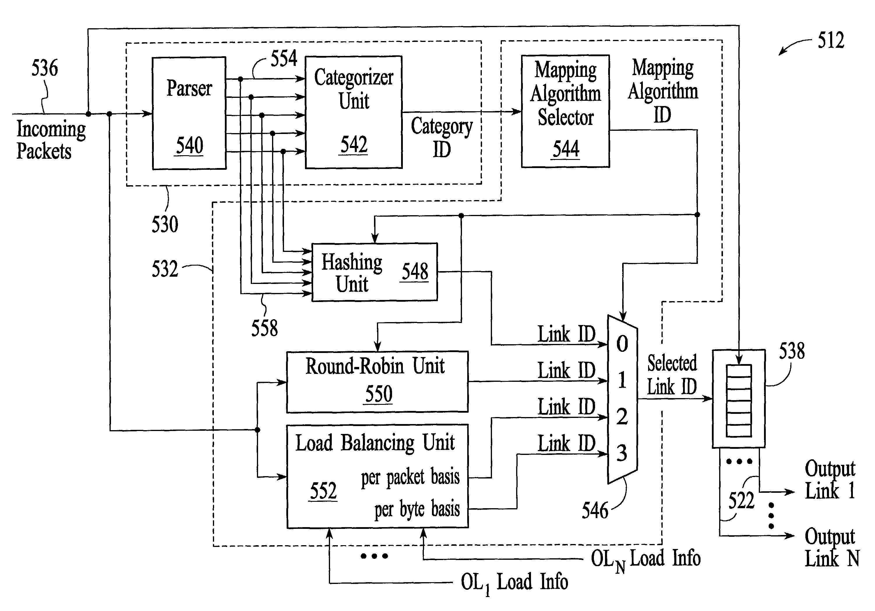
[0012]A system and method for distributing packets from an input link to multiple output links involves categorizing each incoming packet, selecting a mapping algorithm based on the packet category, and then using the selected mapping algorithm for each packet to determine an output link for the respective packet. Categorizing the packets and selecting mapping algorithms based on the packet categories allows for more intelligent and flexible packet distribution among the multiple output links. For example, in-order packets can be distributed such that packets from the same set are sent to the same output link while out-of-order packets can be distributed such that packets are spread more evenly across the multiple output links. Hashing is a technique that can be used to distribute in-order packets from the same set to the same output link. Load balancing and round-robin distribution are two techniques that can be used to distribute out-of-order packets more evenly across the output links.

Problems solved by technology

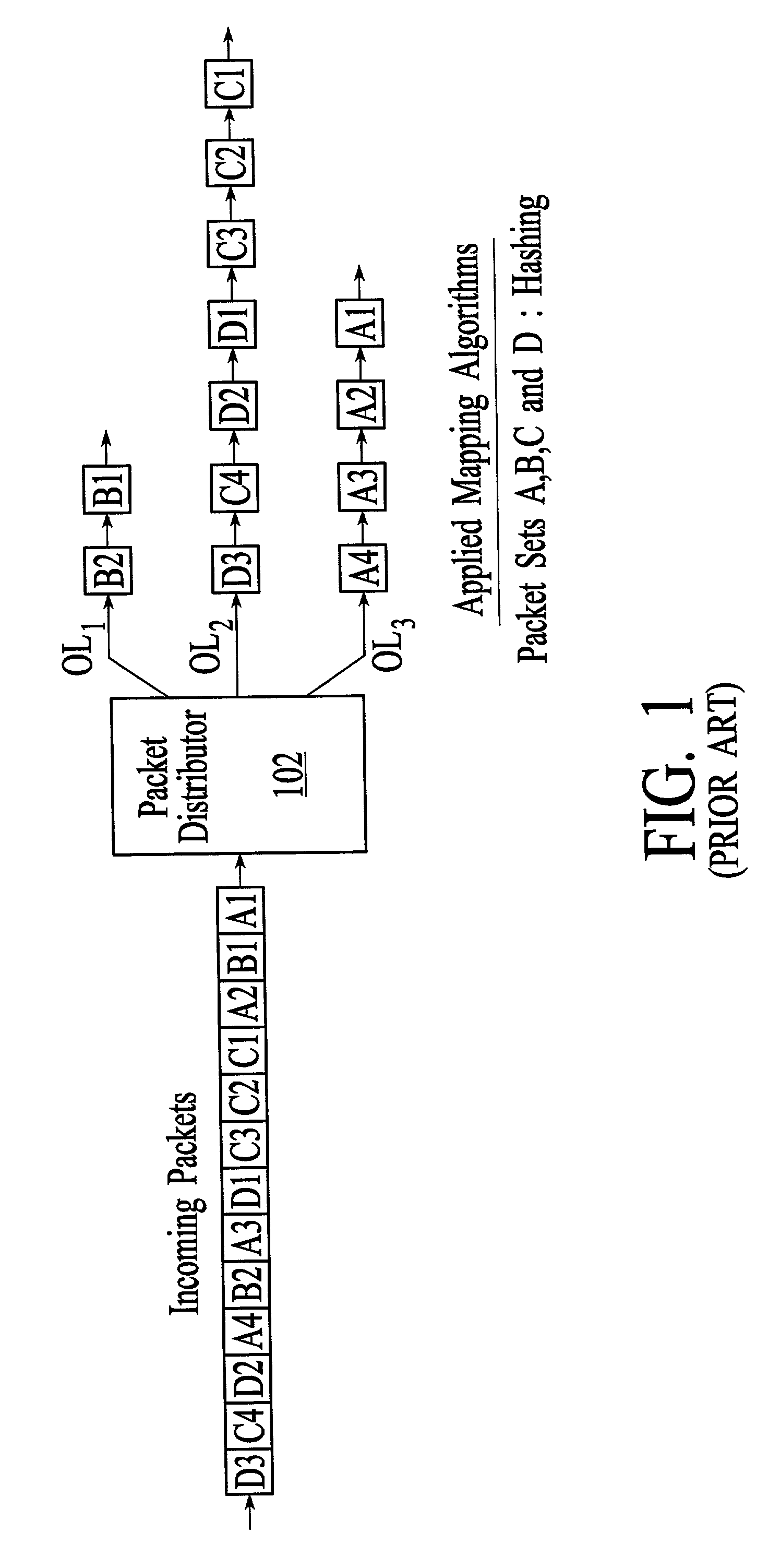
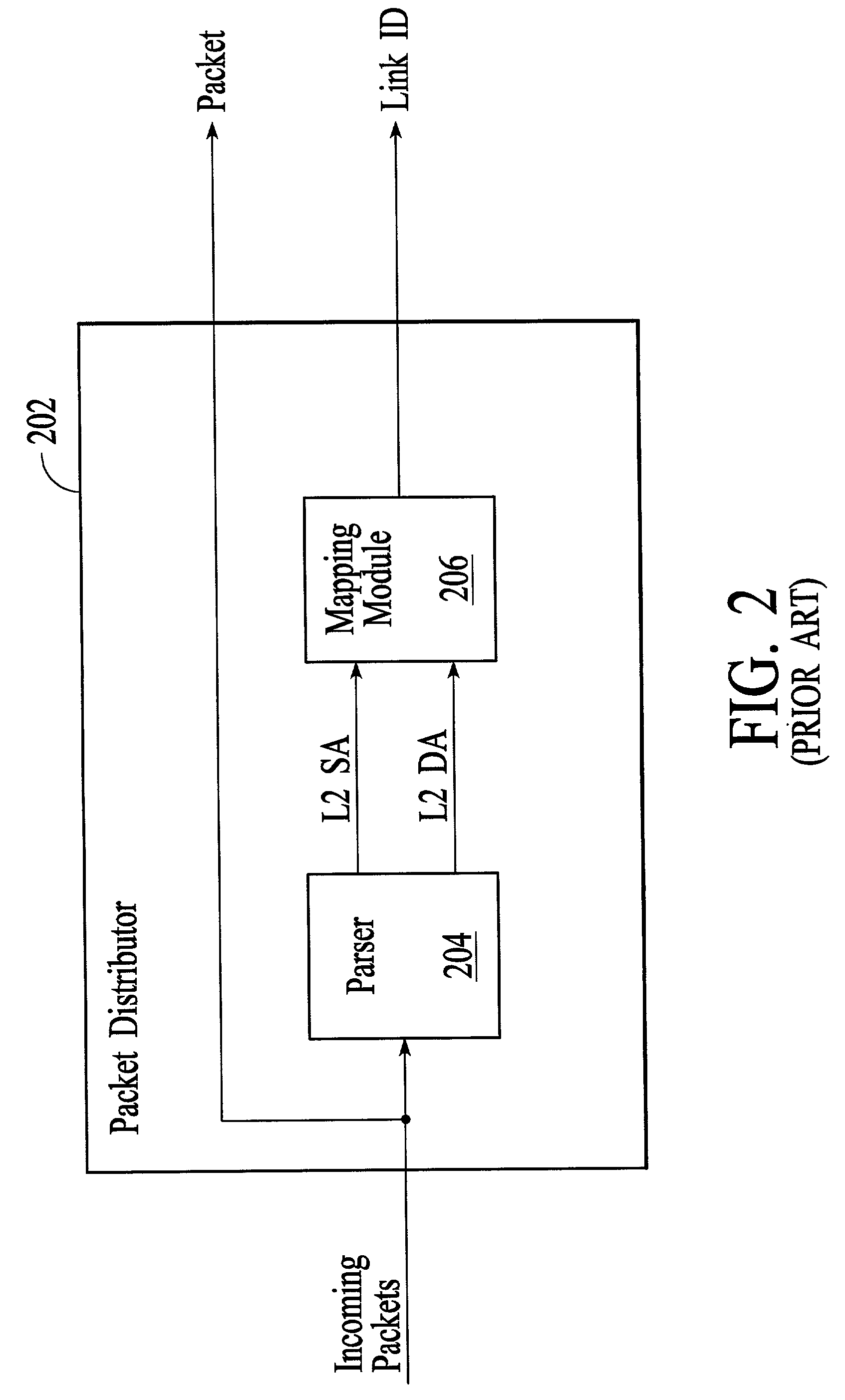
While the approach to packet distribution described with reference to FIGS. 1 and 2 works well when all of the packets are in-order packets, applying the same mapping algorithm to the same field(s) of each incoming packet does not work as well in an environment where some packets are in-order packets and some of the packets are out-of-order packets.
Specifically, the above-described approach does not offer the flexibility to apply different mapping algorithms to different types of packets.

Method used


Image

  • Flexible application of mapping algorithms within a packet distributor
  • Flexible application of mapping algorithms within a packet distributor
  • Flexible application of mapping algorithms within a packet distributor

Examples


Embodiment Construction

[0028]FIG. 3 depicts a switch / router 300 that is connected to a 10 GbE physical link 308. The switch / router has the ability to perform layer 2 switching (also referred to as bridging) of packets and layer 3 routing of packets. The switch / router includes a 10 GbE physical layer unit (PHY) 310, a packet distributor 312, link-specific data link layer packet processors (MACs) 314, link-specific network layer packet processors (PPs) 316, a switch fabric 318, and additional physical links 320. In the embodiment of FIG. 3, the switch / router handles data as Ethernet packets although the invention can be adapted to switch / routers that handle data using other protocols. A brief description of the individual functional units is provided first, followed by a more detailed description of the packet distributor, which is the focus of the invention. Throughout the description, similar reference numbers may be used to identify similar elements.

[0029]The physical links 308 and 320 may include optica...


PUM


Abstract

Distributing packets from an input link to multiple output links involves categorizing each incoming packet, selecting a mapping algorithm based on the packet category, and using the selected mapping algorithm for each packet to determine an output link for the respective packet. If packets are from a category that requires the order of the packets to be maintained, then the selected mapping algorithm causes packets from the same set of packets to be distributed to the same output link. If packets are from a category that does not require the order of the packets to be maintained, then the selected mapping algorithm can cause packets to be distributed more evenly among the multiple output links. Hashing can be used to distribute in-order packets from the same set to the same output link. Load balancing and round-robin distribution can be used to distribute out-of-order packets more evenly across the output links.

Description

FIELD OF THE INVENTION[0001]The invention relates to packet-based communications systems, and more specifically to the distribution of packets from an input link to multiple output links, for example, from one 10 Gigabit Ethernet (GbE) input link to ten 1 GbE output links.BACKGROUND OF THE INVENTION[0002]Packet-based networking architecture is often described in terms of layers, where each layer is responsible for communicating with the same peer protocol running on an opposite machine and for providing services to the layer above it. The layered architecture, referred to as the Open System Interconnect (OSI) model, has been generally defined by the International Organization for Standardization. The layers of the OSI model include the physical layer (layer 1), the data link layer (layer 2), the network layer (layer 3), the transport layer (layer 4), the session layer (layer 5), the presentation layer (layer 6), and the application layer (layer 7). Layers of particular interest here...

Claims


Application Information

Patent Timeline
Patent Type & Authority Patents(United States)
IPC IPC(8): H04L12/28H04L12/56H04L29/06
CPCH04L12/5693H04L45/745H04L47/125H04L47/2441H04L47/34H04L49/30H04L49/602H04L49/9094H04L47/6225H04L69/22H04L49/352H04L49/50H04L47/50
Inventor SCHAUB, MARCRAMAKRISHNAN, BALAKRISHNANMEHTA, KUMAR
Owner LUCENT TECH INC
Why Eureka
Try Eureka