
Current conveyor circuit with improved power supply noise immunity

a conveyor circuit and power supply technology, applied in pulse generators, pulse techniques, instruments, etc., can solve the problem of producing a corresponding increase in the magnitude of noise voltage needed to appear on the power supply, and achieve the effect of improving power supply noise immunity

Active Publication Date: 2007-03-20
NAT SEMICON CORP
View PDF4 Cites 9 Cited by
  • Summary
  • Abstract
  • Description
  • Claims
  • Application Information

AI Technical Summary

Benefits of technology

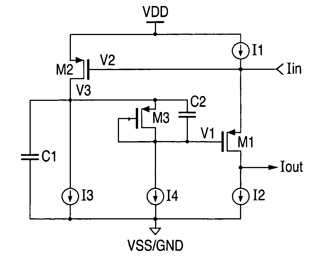
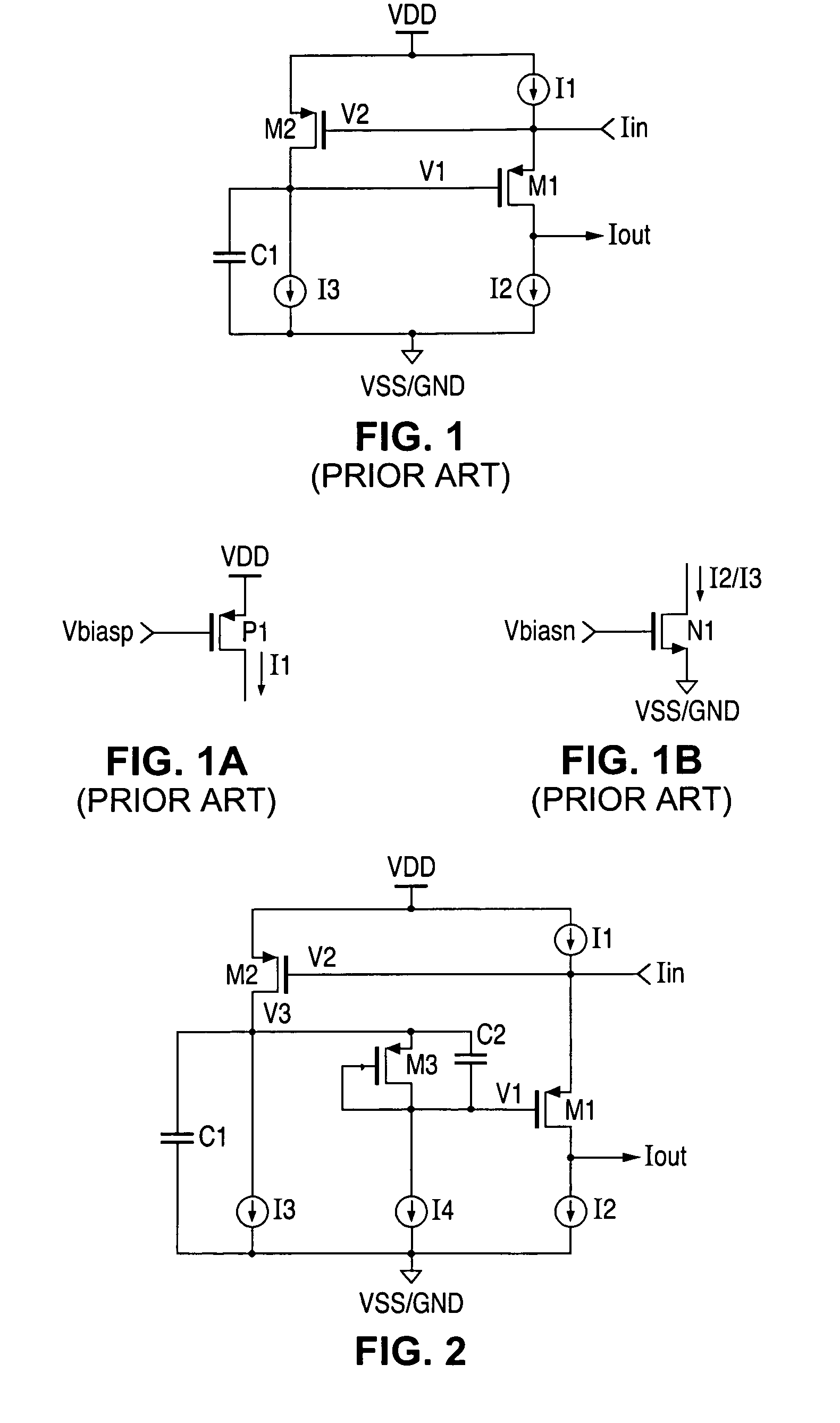
[0009]In accordance with the presently claimed invention, a current conveyor circuit is provided with improved power supply noise immunity. Additional biasing circuitry causes the nominal biasing potential applied to the output circuit to be increased, thereby producing a corresponding increase in the magnitude of noise voltage needed to appear on the power supply before the output signal becomes affected.

Problems solved by technology

Additional biasing circuitry causes the nominal biasing potential applied to the output circuit to be increased, thereby producing a corresponding increase in the magnitude of noise voltage needed to appear on the power supply before the output signal becomes affected.

Method used


Image

  • Current conveyor circuit with improved power supply noise immunity
  • Current conveyor circuit with improved power supply noise immunity
  • Current conveyor circuit with improved power supply noise immunity

Examples


Embodiment Construction

[0015]The following detailed description is of example embodiments of the presently claimed invention with references to the accompanying drawings. Such description is intended to be illustrative and not limiting with respect to the scope of the present invention. Such embodiments are described in sufficient detail to enable one of ordinary skill in the art to practice the subject invention, and it will be understood that other embodiments may be practiced with some variations without departing from the spirit or scope of the subject invention.

[0016]Throughout the present disclosure, absent a clear indication to the contrary from the context, it will be understood that individual circuit elements as described may be singular or plural in number. For example, the terms “circuit” and “circuitry” may include either a single component or a plurality of components, which are either active and / or passive and are connected or otherwise coupled together (e.g., as one or more integrated circ...


PUM


Abstract

A current conveyor circuit with improved power supply noise immunity. Additional biasing circuitry causes the nominal biasing potential applied to the output circuit to be increased, thereby producing a corresponding increase in the magnitude of noise voltage needed to appear on the power supply before the output signal becomes affected.

Description

BACKGROUND OF THE INVENTION[0001]1. Field of the Invention[0002]The present invention relates to current conveyor circuits, and in particular, to current conveyor circuits operating at low voltages with high power supply noise.[0003]2. Description of the Related Art[0004]Referring to FIG. 1, a conventional gain-boosting circuit, often referred to as a current conveyor circuit, includes two transistors, P-type metal oxide semiconductor field effect transistors (P-MOSFETs) M1, M2, and three current sources I1, I2, I3, all interconnected substantially as shown. Referring to FIGS. 1A and 1B, in accordance with well-known current source circuit design techniques, the upper current source I1 can be implemented using a P-type MOSFET P1 with a bias voltage Vbiasp applied at its gate electrode to generate its output current I1. Similarly, each of the lower current sources I2, I3 can be implemented as an N-type MOSFET N1 with an appropriate bias voltage Vbiasn applied at its gate electrode to...

Claims


Application Information

Patent Timeline
IPC IPC(8): H03K17/16H03K3/013
CPCH03F1/30H03F3/345H03F2200/18
Inventor AUDE, ARLO
Owner NAT SEMICON CORP
Learn More