
Flexure mechanism for interface device

a technology of interface device and flexure mechanism, which is applied in the direction of mechanical control device, manual control with single controlling member, instruments, etc., can solve the problems of high cost of mechanism provided in both regular and force feedback interface device, difficult to integrate compelling force feedback into a smaller interface device such as a handheld gamepad or joystick, etc., to achieve low cost, easy manufacturing, stable and accurate

Inactive Publication Date: 2007-03-20
IMMERSION CORPORATION
View PDF48 Cites 113 Cited by
  • Summary
  • Abstract
  • Description
  • Claims
  • Application Information

AI Technical Summary

Benefits of technology

The solution enables the creation of compact, accurate, and stable interface devices that are cost-effective, allowing for precise motion sensing and realistic force feedback, facilitating their integration into handheld devices.

Problems solved by technology

One problem occurring in commercially-available implementations of force feedback devices is that the devices are very bulky.
These features make it difficult to integrate compelling force feedback into a smaller interface device such as a handheld gamepad or joystick.
The mechanisms provided in both regular and force feedback interface devices are typically expensive, complex mechanisms which in turn cause the cost of the interface devices to be expensive.
Handheld interface devices are desired to be low cost items, making it difficult to incorporate accurate position sensing and / or force feedback functionality into these devices.

Method used


Image

  • Flexure mechanism for interface device
  • Flexure mechanism for interface device
  • Flexure mechanism for interface device

Examples


embodiment 100

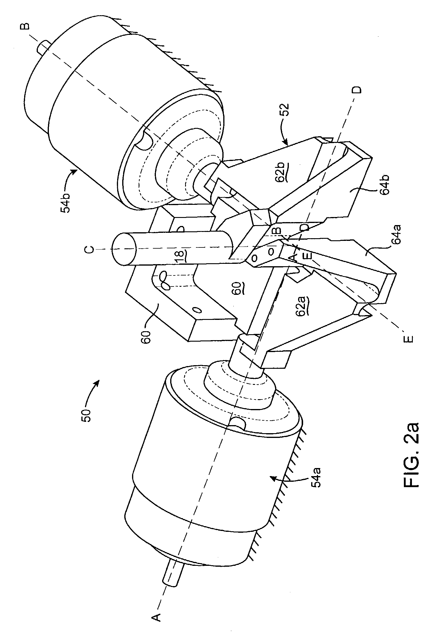
[0065]FIGS. 5a–5b are perspective views of an alternate embodiment 100 of the gimbal mechanism of FIGS. 2 and 3. FIG. 5a shows a view of the top side of the mechanism, and FIG. 5b shows a view of the bottom side of the mechanism. Mechanism 100 operates substantially similarly to the mechanism 25 shown in FIG. 3. A ground member 102 is coupled to ground, extension member 104a is flexibly coupled to ground member 102 by flexure coupling 108a, central member 106a is flexibly coupled to extension member 104a by flexure coupling 110a, central member 106a is coupled to central member 106b by flexure coupling 112, central member 106b is coupled to extension member 104b by flexure coupling 110b, and extension member 104b is coupled to ground member 102 by flexure coupling 108b. Rotation about axes A and B and floating axes D and E are similar to the operation described above with respect to FIG. 3.

[0066]Mechanism 100 differs from the embodiment of FIG. 3 in that central members 106 extend d...

embodiment 150

[0071]FIGS. 6a–6i are side elevational and perspective views of an alternate embodiment 150 of the gimbal mechanism 25 of the present invention. FIGS. 6a and 6b are top and side elevational views, while FIGS. 6c–6i are perspective views of the alternate gimbal mechanism.

[0072]Gimbal mechanism 150 is a unitary flexure, similar to the embodiments described above. An extension member 152a is flexibly coupled to a central member 154a, which is flexibly coupled to central member 154b. Member 154b is flexibly coupled to extension member 152b. However, unlike the embodiment of FIG. 3, the flexible unitary member does not include a ground member, such that the extension members 152 are not coupled together as part of the unitary member. Instead, transducers 156, such as actuators and / or sensors, are connected to the extension members 152 at the connection portions 158, so that three flexure couplings are used instead of the five of FIG. 3. Transducers 156 are shown in the perspective view o...


PUM


Abstract

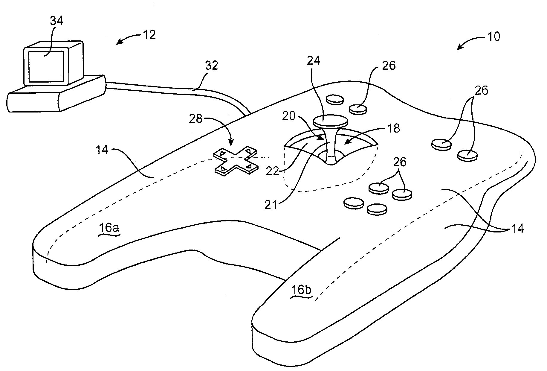
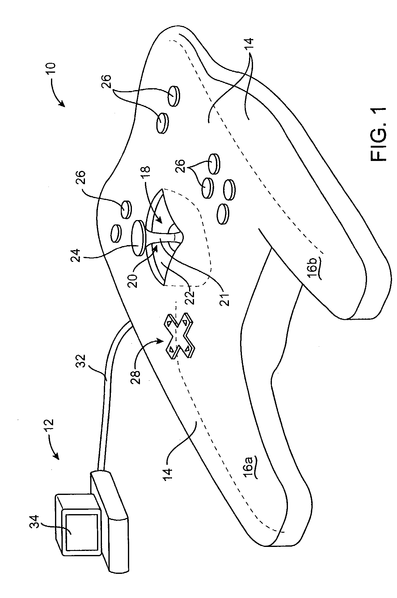
A flexure mechanism for an interface device that interfaces a user with a computer system. An interface device includes a manipulandum physically contacted by the user. A five-bar closed-loop mechanism is coupled to the manipulandum to provide two rotary degrees of freedom to the manipulandum. The mechanism includes members coupled to each other by flexible couplings allowing rotation of the members. In preferred embodiments, four or five of the members are coupled together by flexible couplings that allow bending, thereby forming a unitary piece, where the couplings are oriented along axes of rotation of the mechanism. A senor senses a position of the manipulandum outputs a sensor signal, and in some embodiments actuators are coupled to the mechanism to output a force to the manipulandum in particular degrees of freedom. The manipulandum can be a joystick handle or portion of a sphere, where the device in one embodiment can be a handheld gamepad or similar controller.

Description

CROSS REFERENCE TO RELATED APPLICATIONS[0001]This application is a continuation-in-part of parent patent application Ser. No. 09 / 140,717, filed Aug. 26, 1998 now U.S. Pat. No. 6,201,533 on behalf of Rosenberg et al., which is a divisional of patent application Ser. No. 08 / 560,091, filed Nov. 17, 1995, now U.S. Pat. No. 5,805,140, assigned to the assignee of this present application, and which is incorporated herein by reference in its entirety.BACKGROUND OF THE INVENTION[0002]The present invention relates generally to the interfacing with computer devices by a user, and more particularly to devices used to provide input to computer systems and which provide force feedback to the user.[0003]Humans interface with electronic devices in a variety of applications, and there is a constant need for a more natural, easy-to-use, and versatile interface device. One of those applications includes interacting directly with computer-generated environments. Interface devices are used extensively ...

Claims


Application Information

Patent Timeline
Patent Type & Authority Patents(United States)
IPC IPC(8): G09G5/00G05G9/047G06F3/00G06F3/01G09B23/28
CPCG05G9/047G09B23/285G06F3/016G06F2203/015
Inventor MOORE, DAVID F.MARTIN, KENNETH M.VASSALLO, STEVE P.ROSENBERG, LOUIS B.
Owner IMMERSION CORPORATION
Learn More