Reciprocating microfluidic pump system for chemical or biological agents

a microfluidic pump and biological agent technology, applied in the direction of positive displacement liquid engine, pump, liquid fuel engine, etc., can solve the problems of not being able to achieve major advances in and the earlier efforts to achieve major advances in either miniaturization or biomedical applications. achieve continuous detection, prolong column length, and enhance potential

Inactive Publication Date: 2007-03-27
KANE DAVID +1
View PDF9 Cites 47 Cited by
  • Summary
  • Abstract
  • Description
  • Claims
  • Application Information

AI Technical Summary

Benefits of technology

[0011]Integrating the reciprocating microfluidic pump system of this invention into a microchip allows the invention to be applied to both chemical and biological assays. The microfluidic pump (or “micropump”) system essentially combines the benefits of miniaturization, integration and automation while also solving complex design problems such as controlling and directing sample flow at intersections of micron scale.
[0012]The micropump can use multiple columns and chambers. It is advantageous in that it allows samples to accumulate and mix through a fluid path—and thus allows longer column lengths and continuous detection. Thereby the invention enhances the potential for more accurate data averaging.
[0018]In particular, by including a linking tunnel and passive rather than active valves (as in, e. g., Smits, U.S. Pat. No. 4,938,742), the overall pumping operation is essentially slaved to expansion and contraction of the chamber. This very greatly simplifies electrical connections, synchronization requirements etc. and thereby renders the system far more efficient.
[0043]In particular, the geometry just described imparts to this aspect of the invention an extremely beneficial simplicity and ease of manufacture. The invention is thereby made particularly economic.

Problems solved by technology

While many companies have brought the lab-on-a-chip technology to the forefront of microelectromechanical system (MEMS) applications, these developments heretofore have failed to fully integrate the pumping and detection functions.
An a result, none of these earlier efforts can achieve major advances in either miniaturization or biomedical applications.

Method used


Image

  • Reciprocating microfluidic pump system for chemical or biological agents
  • Reciprocating microfluidic pump system for chemical or biological agents
  • Reciprocating microfluidic pump system for chemical or biological agents

Examples


first embodiment

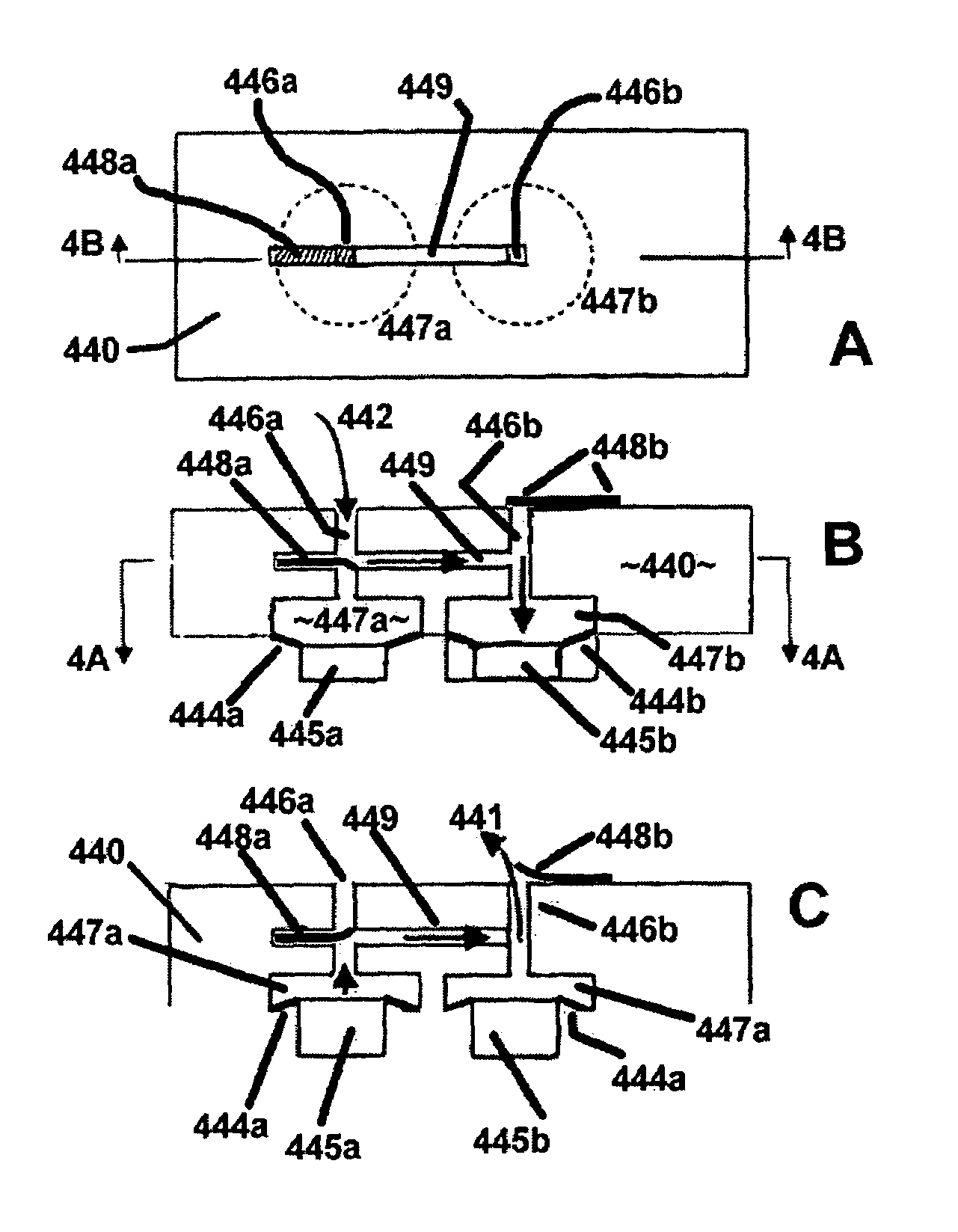
[0052]FIG. 4 is a set of three cross-sectional views, all somewhat schematic or diagrammatic, of a first embodiment that is formed with one or more flappers, for directional flow control, and having a pair of actuator chambers with respectively associated pairs of wells and flappers, each chamber and well being generally analogous to the FIG. 3 single chamber and well—here the topmost or “A” view being in plan, taken along the line 4A—4A in the central or “B” view; and the central and lower, or “B” and “C”, views being taken along the line 4B—4B in the “A” view; and the “B” and “C” views showing the actuator retracted and extended respectively;

second embodiment

[0053]FIG. 5 is a set of three views, generally like those of FIG. 4 but of a second embodiment with flappers, and here having a single actuator chamber but a pair of wells—and with the “A” view being taken along the line 5A—5A of the “B” view, while the “B” and “C” views are taken along the line 5B—5B of the “A” view;

[0054]FIG. 6 is another three-view set, but of a third flapper embodiment, here having not only a single chamber but also a single flapper—and with the “A” view being taken along the line 6A—6A of the “B” view, while the “B” and “C” views are taken along the line 6B—6B of the “A” view;

[0055]FIG. 7 is a pair of diagrams, both highly schematic, that show exemplary preferred embodiments of the invention—the upper or “A” diagram representing a two- (sample and reference) fluorescence and / or polarization configuration of the invention; and the lower “B” diagram being two views of a chemistry / biology chip with a pump and waveguide system (the overall chip array 65 includes a...


PUM


Abstract

A miniature pump has at least one controllable expansion-and-contraction chamber, and associated pair of tiny ducts interconnecting a fluid source and destination. The ducts communicate with the chamber(s); an linking tunnel links the ducts. Valves interact with fluid pressures due to expansion and contraction, imposing directionality on flow in the ducts and tunnel. Preferences: making the valve a passive flapper, implanting the pump in a creature, making the source a medication reservoir for supplying the creature; making the source a fuel tank and destination a tiny engine; making the source provide a specimen for assay and destination an observation slide; human or automatic examination of the slide under a microscope (e. g. electron microscope); making the source a reagent and destination a process stream; making the source a colorant and destination a colorant application system. Preferably included is an optical channel with intersecting fluid duct for optically monitoring pumped fluid.

Description

RELATED PATENT DOCUMENT[0001]This patent document claims priority from provisional application 60 / 327,759, filed Oct. 5, 2001.[0002]Wholly incorporated by reference herein are copending, coowned provisional applications Ser. 60 / 228,883, filed Aug. 29, 2000, and 60 / 327,760, filed Oct. 5, 2001. The first of these applications later became the basis of U.S. patent application Ser. No. 10 / 142,654—which issued Feb. 15, 2005 as U.S. Pat. No. 6,856,718; and the second (a companion case to this one) became U.S. patent application Ser. No. 10 / 265,278—eventuating as issued U.S. Pat. No. 6,934,435.BACKGROUND[0003]There has been an ongoing research effort to integrate microfluidic-based systems with appropriate sensors and analytical components. An objective has been effective miniaturization of chemical and biological assays, with the creation of a lab-on-a-chip technology.[0004]A defining attribute of microassays is small amounts of gas or liquid material required for sample reaction. This ec...

Claims


Application Information

Patent Timeline
Patent Type & Authority Patents(United States)
IPC IPC(8): F04B17/00F04B19/00F04B37/02F04B43/04F04F99/00
CPCF04B43/043F04B19/006
Inventor KANE, DAVIDMCGRUER, NICOI
Owner KANE DAVID
Why Eureka
Try Eureka