
Process for electrostatographic reproduction

a technology of electrostatographic reproduction and electrostatographic imaging, applied in the direction of electrographic process apparatus, instruments, developers, etc., can solve the problems of low gloss, subtle variations in gloss, and hidden defects, and achieve low surface energy, low gloss, and high desirable low gloss images

Active Publication Date: 2007-03-27
EASTMAN KODAK CO +1
View PDF58 Cites 13 Cited by
  • Summary
  • Abstract
  • Description
  • Claims
  • Application Information

AI Technical Summary

Benefits of technology

[0023]The present invention allows for the use of wear resistant and low surface energy fluoroelastomer, in generating highly desirable low gloss images that do not produce glare. Image defects, such as release oil artifacts and differential wear from skives or sensors contacting the roller surface, are not visible.
[0024]The benefits as indicated are not dependent upon the substrate surface to which the toner is fused. Particularly, they are obtained with paper regardless of its roughness, or whether it is coated or uncoated; at least, low gloss is provided over a range of substrate roughness. Still further, generation of low gloss is maintained despite wear on the fuser member surface. And even on rough substrates, the gloss obtained is uniform, or at least essentially or substantially uniform.

Problems solved by technology

Subtle defects can be seen in these images, particularly defects that cause subtle variations in gloss.
Varying types of paper have different levels of roughness, and glossy images produced on rough paper often produce differential gloss.
This is particularly a problem in high speed digital printing, where high paper speeds require short fusing times. In the faster printers, when the image is high gloss there is often not time to allow a uniform gloss image on rough papers.
Unfortunately, silicone rubbers wear easily when employed for this purpose; after a period of use, the action of the paper or other media passing through a high pressure nip wears a polysiloxane elastomer fuser surface.
The silicone rubbers' low wear resistance as fuser member surfaces accordingly limits fuser member life.
Further, although treatment with a polysiloxane release fluid during use of the fuser member enhances its ability to release toner, the fluid causes the silicone rubber to swell.
This fluid absorption is a particular factor that shortens fuser member life; fluid treated portions tend to swell and wear and degrade faster.
Fuser members with polysiloxane elastomer fusing surfaces accordingly have a limited life.
However, there are disadvantages associated with the use of both.
However, fluorocarbon resins are less flexible and elastic than polysiloxane elastomers, and are unsuitable for producing high image quality images.
Fluorocarbon resins typically have a high modulus, and cannot evenly contact rough papers; they therefore provide varying gloss within the same image.
The high modulus also tends to produce images with objectionable mottle, and contributes to high gloss; specifically, with both a smooth surface and high modulus, there will be high gloss in addition to the objectionable mottle.
However, due to their relatively greater hardness as compared with that of the silicone rubbers, fluoroelastomers also typically produce objectionably high gloss images.
Increasing the amount of heat conducting filler content in the fusing surface layer, by providing more reactive sites for the toner, therefore increases toner offset, and accordingly also increases contamination of the fuser member.

Method used


Image

  • Process for electrostatographic reproduction
  • Process for electrostatographic reproduction
  • Process for electrostatographic reproduction

Examples


example 1

[0263]A fuser roller was prepared in substantially the same manner as that of Comparative Example 1, except for the following differences. Specifically, 40 grams of Composition 3 were employed instead of 80 grams of Composition 1. Further, 150 grams of MEK, 1.8 grams of PS513, and 0.4 grams of VITON™ Curative No. 50 were employed, instead of the amounts of these materials as specified in Example 1. Yet additionally, in place of adding the PS513 and VITON™ Curative No. 50 30 minutes before ring coating, and instead of adding the VITON™ Curative No. 50 to the full amount of the solution previously prepared, the following sequence was employed, with the amounts as indicated: the 1.8 grams of PS513 were added to the solution of Composition 3 in MEK; 24 hours after this addition of PS513, 17.7 grams of SFR-100 were added; 7 hours after addition of the SFR-100, a 97 grams portion of the solution was taken, and the VITON™ Curative No. 50 was added to this portion; and the ring coating was ...

example 2

[0264]A fuser roller was prepared in substantially the same manner as that of Example 1, except the amount of VITON™ Curative No. 50 employed was 1.26 grams, and that the amount of solution taken after addition of the SFR-100 was 98 grams, with the indicated VITON™ Curative No. 50 being added to this portion. The thickness of the fluoroelastomer coating was measured by the same manner as in Comparative Example 1, and determined to be 3.74 mils thick.

example 3

[0265]A fuser roller was prepared in substantially the same manner as that of Example 1, except for the following differences. Specifically, 65 grams of Composition 4 were employed in place of 40 grams of Composition 3, and 155 grams of MEK, 2.123 grams of PS513, 2.95 grams of VITON™ Curative No. 50, and 21.23 grams of SFR100 were employed in place of the amounts described in Example 1. Additionally, after addition of the SFR-100, the VITON™ Curative No. 50 was added to the entire amount of solution. The thickness of the fluoroelastomer coating was measured by the same manner as in Comparative Example 1, and determined to be 4.64 mils thick.


PUM


Abstract

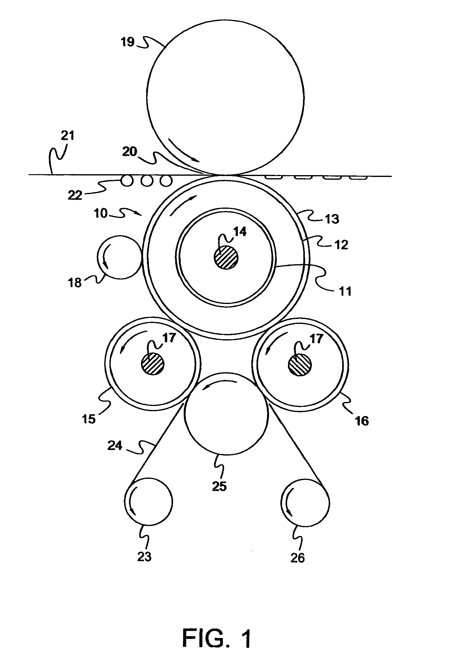
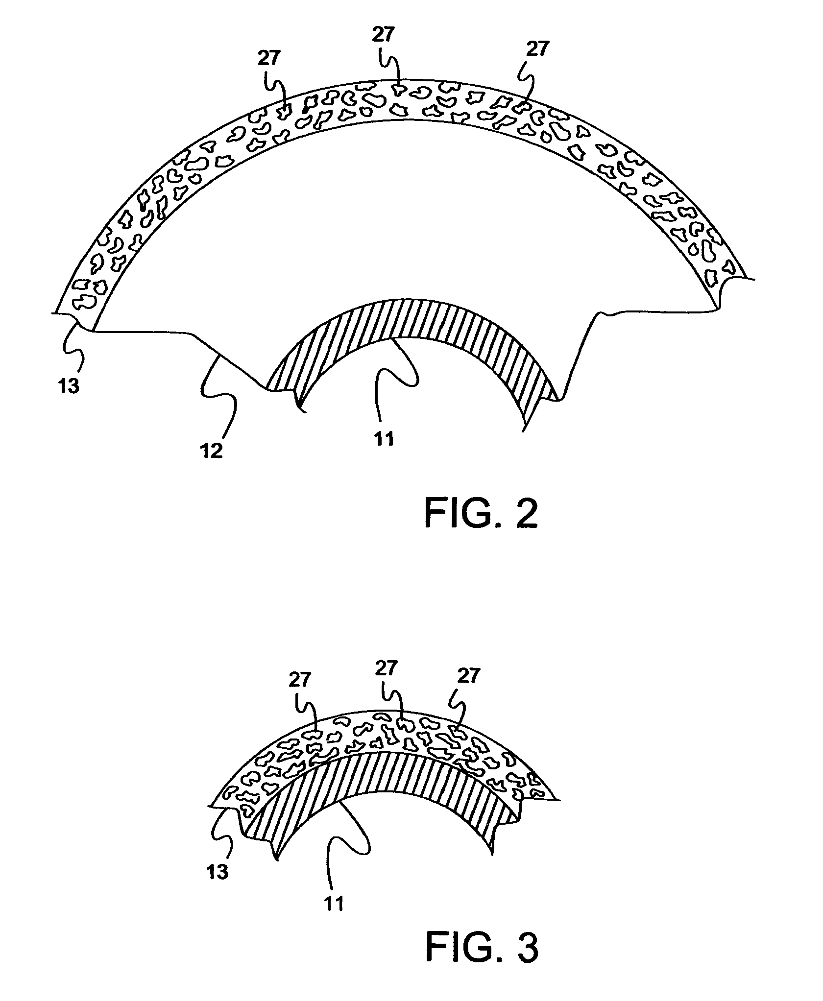
A process for fusing toner to paper. The toner fusing system for conducting this process includes a fuser roller consisting of a base, and a fusing surface layer that includes both a fluoroelastomer continuous phase, and also a discontinuous phase dispersed through the continuous phase in the form of domains.

Description

CROSS-REFERENCE TO RELATED APPLICATIONS[0001]This application claims benefit under 35 USC §119(e) of prior co-pending U.S. Provisional Patent Application Ser. No. 60 / 425,626, filed Nov. 13, 2002. This provisional patent application is incorporated herein in its entirety, by reference thereto.[0002]Filed concurrently with this application are the application entitled “Layer Comprising Nonfibrillatable and Autoadhesive Particles, and Method of Preparation”, U.S. Ser. No. 10 / 692,440 filed Oct. 23, 2003, and the application entitled “Fuser Member And Fuser Member Surface Layer”, U.S. Ser. No. 10 / 691.778 filed Oct. 23, 2003. These two concurrently filed applications are incorporated herein in their entireties, by reference thereto.BACKGROUND OF THE INVENTION[0003]1. Field of the Invention[0004]The present invention relates to electrostatographic imaging and recording apparatus, and to assemblies in these apparatus for fixing toner to the substrates. The present invention relates particul...

Claims


Application Information

Patent Timeline
Patent Type & Authority Patents(United States)
IPC IPC(8): G03G13/20
CPCG03G15/2057
Inventor PICKERING, JERRY A.BARUCH, SUSAN C.
Owner EASTMAN KODAK CO
Learn More