
Liquid crystal based polarimetric system, a process for the calibration of this polarimetric system, and a polarimetric measurement process

a polarimetric system and liquid crystal technology, applied in the direction of polarisation-affecting properties, optical radiation measurement, instruments, etc., can solve the problems of inadequate calibration methods, and achieve the effects of wide enough acceptance angle, fast data acquisition, and simple and compact structur

Active Publication Date: 2007-03-27
CENT NAT DE LA RECHERCHE SCI +1
View PDF5 Cites 11 Cited by
  • Summary
  • Abstract
  • Description
  • Claims
  • Application Information

AI Technical Summary

Benefits of technology

[0027]A purpose of the present invention is to remedy the shortcomings mentioned above and to propose a polarimetric system having one or more of the following features and advantages: namely, polarization modulation by liquid crystals only, with no mechanically moving parts, providing a wide enough acceptance angle for typical imaging applications, a simple and compact design including optimization with respect to error propagation, and a fast data acquisition, to be usable for measurements in real time.
[0030]In a complete operation mode: the complete Mueller matrix (M) of any sample under study, either in transmission or in reflection.The optimization of the PSG and PSD configurations with respect to error propagation implies that the states generated by the PSG (and those “filtered” by the PSD) are not “simple” ones, such as linear or circular, and thus usual calibration methods are not really adequate. The invention includes therefore an objective calibration process for each of the two types of measurement cited above, said calibration processes being at once accurate, rapid and easy to implement.
[0077]calculating the product (AIoW)−1(AR(−θp)MpR(θp)W) for each reference sample p in order to obtain an experimental matrix (Cp) and determining Mp, or, more precisely, the values of its parameters τp, Ψp and Δp, independently of the angles θp through the eigenvalues of Cp, which are identical to those of Mp. This allows a very accurate characterization of each sample in situ, during the calibration itself,

Problems solved by technology

The optimization of the PSG and PSD configurations with respect to error propagation implies that the states generated by the PSG (and those “filtered” by the PSD) are not “simple” ones, such as linear or circular, and thus usual calibration methods are not really adequate.

Method used


Image

  • Liquid crystal based polarimetric system, a process for the calibration of this polarimetric system, and a polarimetric measurement process
  • Liquid crystal based polarimetric system, a process for the calibration of this polarimetric system, and a polarimetric measurement process
  • Liquid crystal based polarimetric system, a process for the calibration of this polarimetric system, and a polarimetric measurement process

Examples


Embodiment Construction

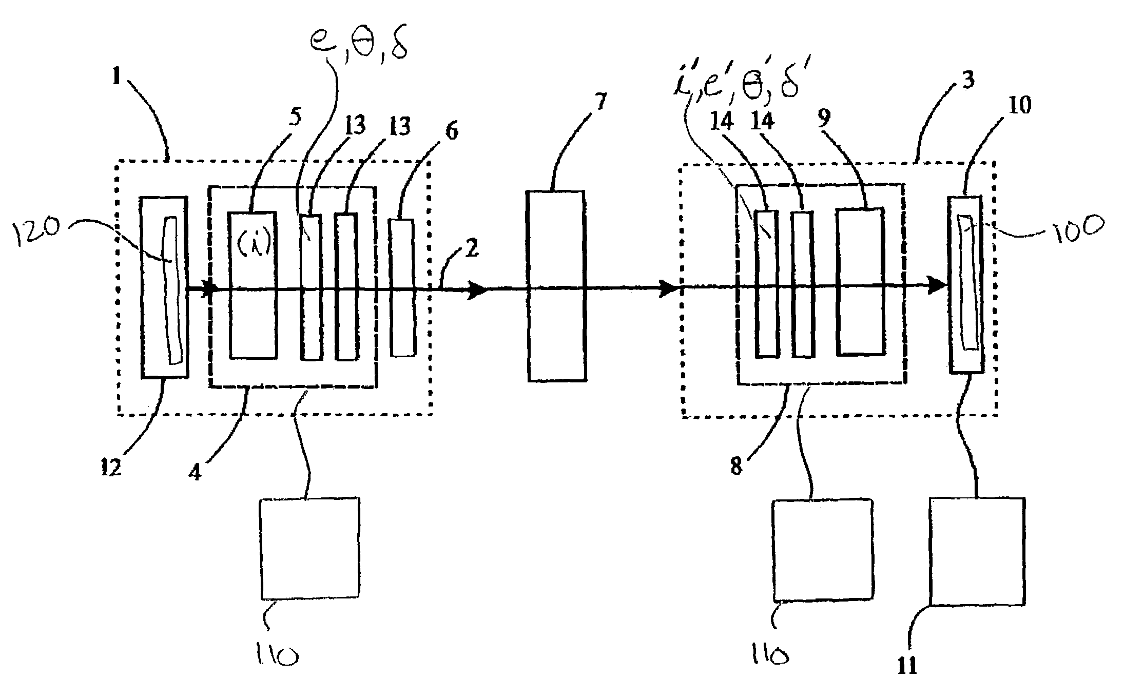
[0134]FIG. 1 shows a polarimetric system according to an embodiment of the invention. It contains an excitation section 1 emitting a light beam 2 and an analysis section 3.

[0135]The excitation section 1 comprises a polarization state generator 4 (PSG) through which passes the light beam 2. The polarization state generator 4 comprises a polarizer 5 that linearly polarizes the light beam 2 along a polarization direction (i).

[0136]First optical means 6 defines the geometry of the beam 2 at the sample 7.

[0137]The analysis section 3 comprises a polarization state detector 8 (PSD) containing an analyzer 9 and detection means 10 for detecting the light beam 2.

[0138]In a particular embodiment, the detection means 10 comprises a multipoint photosensitive detector that produces electrical signals sent to a processing unit 11. Said detection means 10 are adapted to polarimetric imaging and the multipoint photosensitive detector is advantageously a charge coupled detector (CCD).

[0139]The polari...


PUM


Abstract

A liquid crystal based polarimetric system, a process for the calibration of this polarimetric system, and a polarimetric measurement process intended for measuring the representative parameters of a sample in which the polarimetric system contains an excitation section emitting a light beam that passes through a polarization state generator (PSG) and onto a sample. After reflection or transmission by the sample, the beam goes through an analysis section with a polarization state detector (PSD). The PSG and PSD each have a first and a second liquid crystal elements LCj (j=1,2) having, for each LCj element of the PSG (respectively for each LCj element of the PSD), an extraordinary axis making an angle θj (resp. θ′j) with respect to the polarization direction (i), and a retardation δj (resp (δ′j) between its ordinary and extraordinary axes, the liquid crystals LCj elements being positioned in reverse order in the PSD with respect to the LCj elements of the PSG.

Description

BACKGROUND OF THE INVENTION[0001]The invention relates to a liquid crystal based polarimetric system for analyzing a sample, a process for the calibration of this polarimetric system and a polarimetric measurement process.DESCRIPTION OF THE RELATED ART[0002]In order to measure parameters which are representative of a sample (for example, of its composition and thickness), it is conventional to make use of an ellipsometer.[0003]Ellipsometry is a powerful non invasive probe in which reflectance or transmittance data are measured by electromagnetic radiation outcoming from a sample. Briefly, the surface of a studied sample is illuminated by a photon beam that is reflected or transmitted and the polarization state of the outcoming beam is compared to that of the incident beam.[0004]This conventional ellipsometry method proves satisfactory when the reflected light is still totally polarized (even though elliptically), which is indeed the case, among other examples, for isotropic layers w...

Claims


Application Information

Patent Timeline
IPC IPC(8): G01J4/00G01J4/04G01N21/21G02F1/13
CPCG01N21/211G01J4/04
Inventor DREVILLON, BERNARDDE MARTINO, ANTONELLO
Owner CENT NAT DE LA RECHERCHE SCI
Learn More