Illumination optical unit liquid crystal projector and production method of liquid crystal projector

a technology of liquid crystal projector and illumination optical unit, which is applied in the direction of lighting optical unit, television system, lighting and heating apparatus, etc., can solve the problems of difficult assembly cost reduction, large number of optical systems, and decrease in so as to reduce assembly costs, increase the effective area of light incident, and shorten the optical path length of lighting optical uni

Inactive Publication Date: 2007-04-03
SONY CORP
View PDF11 Cites 9 Cited by
  • Summary
  • Abstract
  • Description
  • Claims
  • Application Information

AI Technical Summary

Benefits of technology

[0022]Thus, it becomes possible to reduce the optical path length of the lighting optical unit by reducing the F number of this optical system.
[0049]According to this liquid-crystal projector (second liquid-crystal projector according to the present invention), from exactly the same reason that has been set forth with respect to the aforementioned second lighting optical unit according to the present invention, the optical path length can be shortened and the optical systems can be made common in exactly the same manner as those in the aforementioned first lighting optical unit according to present invention; and decrease in a quantity of light irradiated on the object due to the aberration of the optical assembly that diverges converged light is prevented without increasing the number of the optical assemblies and without causing the outside dimension of the lighting optical unit to increase (accordingly, without causing the whole of the liquid-crystal projector to become large in size), whereby efficiency in utilizing light from the light-source lamp can be enhanced.

Problems solved by technology

Therefore, there is a possibility that a quantity of light incident on the effective area will decrease.
(a) In the liquid-crystal projector using the liquid-crystal panel with ML, when a numerical aperture of the optical system in the lighting optical unit for irradiating light from the light-source lamp on the liquid-crystal panel in a uniform and / or convergent manner is reduced, the F number of this optical system becomes large. Specifically, assuming that the F number of the optical system in the lighting optical unit of the liquid-crystal projector using the liquid-crystal panel without ML falls within a range of approximately 2.2 to 2.5, then the F number of the optical system in the lighting optical unit of the liquid-crystal projector using the liquid-crystal panel with ML becomes 3 or larger.
Accordingly, since the optical assemblies cannot be made common to those optical systems, it is difficult to reduce costs of assemblies.
Therefore, it is difficult to make a manufacturing operation more efficient.

Method used


Image

  • Illumination optical unit liquid crystal projector and production method of liquid crystal projector
  • Illumination optical unit liquid crystal projector and production method of liquid crystal projector
  • Illumination optical unit liquid crystal projector and production method of liquid crystal projector

Examples


Embodiment Construction

[0070]Hereinafter, embodiments in which the present invention is applied to a liquid-crystal projector with ML will be specifically described with reference to the drawings.

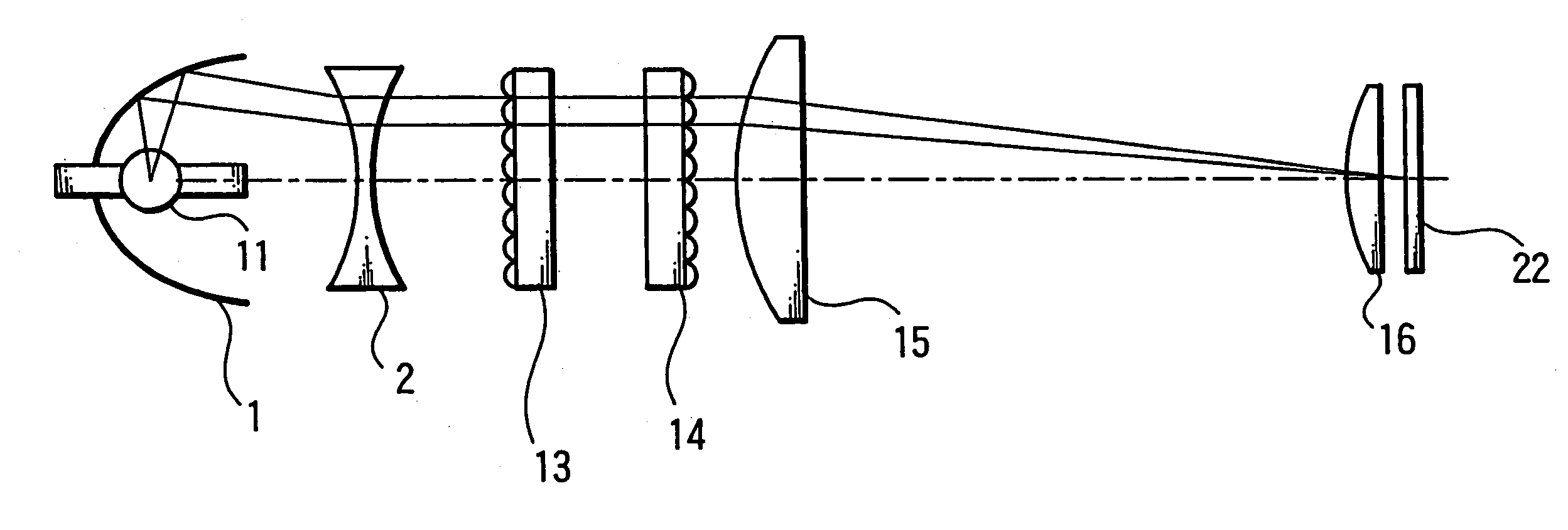
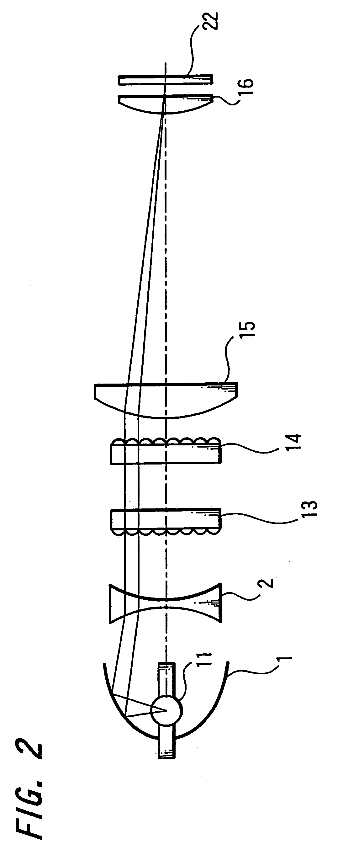
[0071]FIG. 2 is a diagram showing an example of an arrangement of a main portion of a first lighting optical unit according to the present invention, wherein elements and parts identical to those in FIG. 1 are denoted by the same reference numerals.

[0072]In this lighting optical unit, the light-source lamp 11 is detachably attached to an elliptic reflector 1 having a reflection surface shaped like an ellipse. The elliptic reflector 1 reflects light emitted from the light-source lamp 11 to provide converged light.

[0073]The concave lens 2 is disposed on the side of the liquid-crystal panel with ML 22 opposite to the elliptic reflector 1. The concave lens 2 makes converged light from the elliptic reflector 1 diverge in order to provide a bundle of approximately parallel rays.

[0074]On the side of liquid-crystal panel...


PUM

PropertyMeasurementUnit
diameteraaaaaaaaaa
areaaaaaaaaaaa
optical path lengthaaaaaaaaaa

Abstract

A lighting optical unit having an optical system for irradiating light from a light-source lamp on a predetermined object in a uniform and / or convergent manner includes a reflector for reflecting light from the light-source lamp to provide converged light and an optical assembly for collimating this converged light to provide a bundle of approximately parallel rays, wherein the bundle of approximately parallel rays is made to enter the optical systeml. Thus, in a liquid-crystal projector using a transmission type liquid-crystal panel with micro-lens, while a demand for increasing a quantity of light incident on an effective area of pixel of a liquid-crystal panel is being satisfied, the lighting optical unit can be made compact in size.

Description

TECHNICAL FIELD[0001]The present invention relates to a lighting optical unit, a liquid-crystal projector and a method of manufacturing liquid-crystal projectors.BACKGROUND ART[0002]In liquid-crystal projectors using a transmission type liquid-crystal panel as a light modulating element, there exists a liquid-crystal projector in which a micro-lens (hereinafter also described as “ML”) is provided on the surface of a liquid-crystal panel corresponding to each pixel in order to increase a quantity of light incident on an effective area of pixel.[0003]FIG. 1 is a diagram showing an example of a conventional arrangement of a main portion of a lighting optical unit in a liquid-crystal projector using a liquid-crystal panel with ML compared with a lighting optical unit of a liquid-crystal projector using a liquid-crystal panel without ML.[0004]In the lighting optical unit of the liquid-crystal projector using the liquid-crystal panel without ML, as shown in FIG. 1A, light emitted from a l...

Claims


Application Information

Patent Timeline
Patent Type & Authority Patents(United States)
IPC IPC(8): G03B21/20G02B27/10G02F1/00G02F1/1335G03B21/28H04N5/74G02B19/00G02B27/00G02B27/14G02F1/13G03B21/00G03B21/14H04N9/31
CPCG02B27/0927G02B27/0961G02B27/1046G02B27/145G02B27/149G03B21/14H04N9/3105H04N9/315H04N9/3197G03B21/208
Inventor KATSUMATA, MASAOOKAMURA, TETSURO
Owner SONY CORP
Why Eureka
Try Eureka