Fastening arrangement for a split casing

Inactive Publication Date: 2007-04-03
MITSUBISHI HEAVY IND LTD
View PDF12 Cites 36 Cited by
  • Summary
  • Abstract
  • Description
  • Claims
  • Application Information

AI Technical Summary

Benefits of technology

[0023]According to this aspect of the present invention, a casing of a hydraulic machine such as a turbine, a compressor or a pump is constructed as a horizontally split type casing. Also in this aspect of the invention, the shaft tensile force of the fastening bolt is transferred to the upper casing through the sleeve in order to increase the contac

Problems solved by technology

However, in some cases, problems occur when the fastening arrangement using the flanges as illustrated in FIG. 7 is used for the horizontally split type casings of hydraulic machines such as turbines or compressors.
However, in the turbines and compressors, since the temperature of the fluid passing through the casings is high, the temperature of the respective portions of the casings becomes high.
When a large thermal stress is generated, the casing tends to deform and concentricity of the cross section of the casing cannot be maintained.
Further, in the turbines and compressors, the temperature of the fluid passing through the machines changes considerably due to a change in the operating load.
This causes a large temperature difference between the flanges and other casing portions when the rate of the change in the temperature of the fluid in the casing is high.
Therefore, if the casing is provided with flanges having a large thickness, distortion of the casing may occur when the temperature of the fluid changes.
This may cause damage to the machine.
However, in the hydraulic machines such as turbines

Method used


Image

  • Fastening arrangement for a split casing
  • Fastening arrangement for a split casing
  • Fastening arrangement for a split casing

Examples


Example

(1) First Embodiment

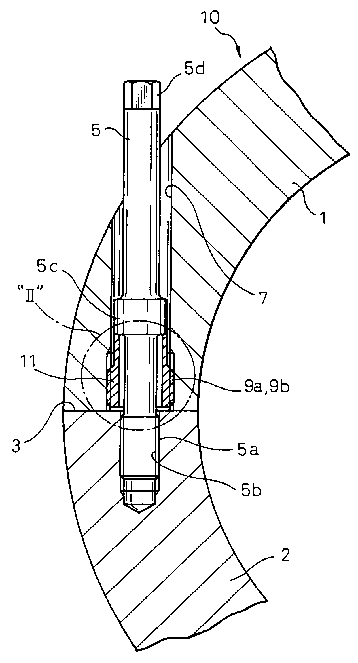
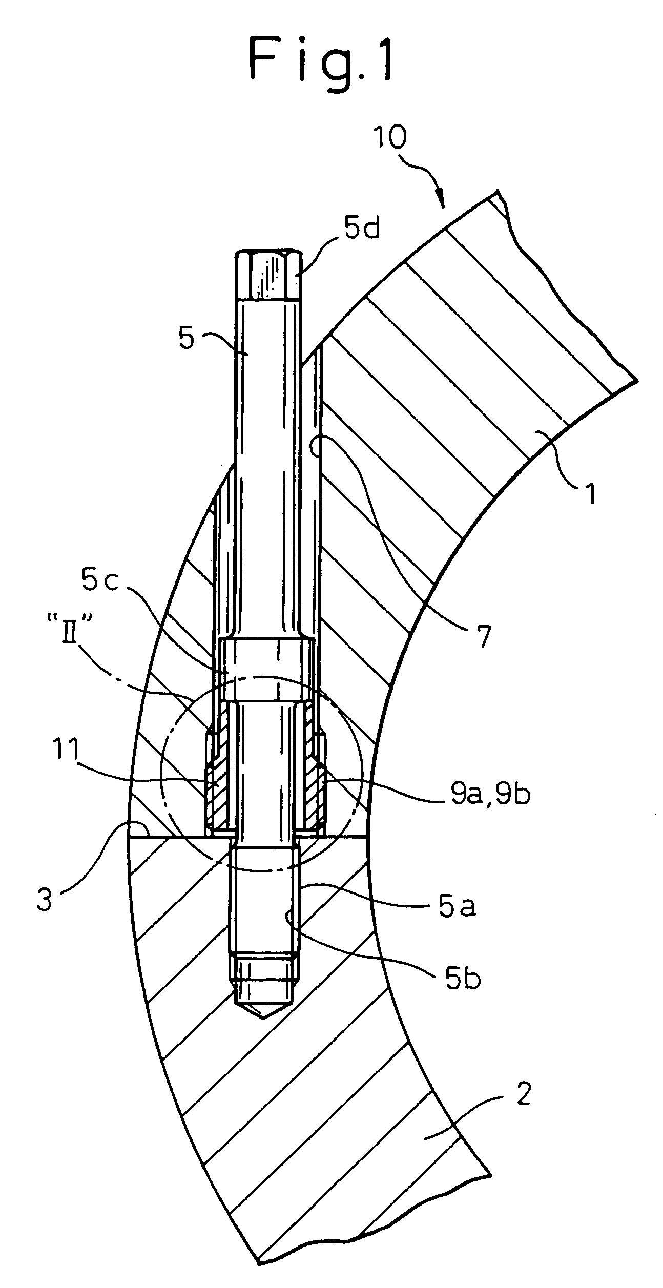
[0036]FIG. 1 illustrates a first embodiment of a fastening arrangement for a flangeless casing according to the present invention.

[0037]FIG. 1 is a sectional view of a casing of a gas turbine taken along the plane perpendicular to the center axis. The casing 10 of the gas turbine in FIG. 1 is constructed as a horizontally split type flangeless casing. More specifically the casing 10 in FIG. 1 is a cylindrical shape and split into two casing halves 1 and 2 by a plane including the center axis. The casing half 1 (hereinafter referred to as the “upper casing”) and the casing half 2 (hereinafter referred to as the “lower casing”) are coupled by joining joint faces 3 and fastened to each other firmly.

[0038]In FIG. 1, reference numeral 5 designates a plurality of fastening bolts for fastening the upper casing 1 and lower casing 2 together. In this embodiment, a screw thread 5a is formed at lower end portion of each fastening bolt 5. The fastening bolts 5 pass through b...

Example

[0055]FIG. 4 is a sectional view similar to FIG. 1 illustrating a second embodiment of the present invention. In FIG. 4, the reference numerals the same as those in FIG. 1 designate similar elements.

[0056]In this embodiment, a cylindrical sleeve similar to that in the first embodiment is used. However, although the sleeve 11 in the first embodiment is screwed into the bolt hole 7 from the joint face 3 side thereof, the sleeve 11 in this embodiment is screwed into the bolt hole 7 from the side thereof opposite to the joint face 3 and fitted inside the upper portion of the bolt hole 7. Further, the upper portion of the sleeve 11 protrudes from the bolt hole 7.

[0057]In this embodiment, an ordinary Allen screw the same as that in FIG. 8 is used in this embodiment. The diameter of the bolt head of an Allen screw is larger than the required diameter of the sleeve 11 as explained in the previous embodiment. Therefore, in order to avoid an increase in the diameter of the bolt hole 7 due to ...

Example

(3) Third Embodiment

[0058]FIG. 5 is sectional view similar to FIG. 1 but illustrating a third embodiment of the present invention. In FIG. 5, the reference numerals the same as those in FIGS. 1 and 2 designate similar elements.

[0059]In this embodiment, similar to the first embodiment, the sleeve 11 is screwed into the bolt hole 7 from the joint face 3 side. However, the shape of the bolt hole 7 in this embodiment is different from that of the first embodiment. Namely, the diameter of the bolt hole 7, is enlarged at the lower portion thereof in order to accommodate the sleeve 11 and the diameter of the bolt hole 7 at the upper portion thereof is reduced to a value slightly larger than the diameter of the shaft portion 5s of the fastening bolt 5.

[0060]In contrast with the first embodiment, in order to fastening the casing 10, the fastening bolt 5 is first inserted into the bolt hole 7 from the joint face 3 side, then, the sleeve 11 is screwed into the bolt hole 7 from the joint face 3...


PUM

PropertyMeasurementUnit
Forceaaaaaaaaaa
Diameteraaaaaaaaaa
Lengthaaaaaaaaaa

Abstract

A casing of a hydraulic machine such as a gas turbine is formed as a horizontally split type flangeless casing. The flangeless casing consists of an upper casing and a lower casing joined together at joint faces and fastened by fastening bolts. The fastening bolt has a screw thread which engages the threaded hole on the joint face of the lower casing. A bolt hole having an internal screw thread and through which the fastening bolt passes is provided in the upper casing. A sleeve having an external screw thread is fitted into the bolt hole of the upper casing by engaging the external screw of the sleeve with the internal sleeve of the bolt hole. An enlarged diameter portion is formed on a shaft of the fastening bolt at the portion where the enlarged diameter portion abuts an upper end face of the sleeve when the fastening bolt is screwed into the threaded hole in the lower casing. When the fastening bolt is tightened, the shaft tensile force of the bolt is received by the abutment of the enlarged diameter portion and the upper end face of the sleeve and, then, transferred from the sleeve to the upper casing through the engagement of the external screw thread of the sleeve and the internal screw thread of the bolt hole of the upper casing and generates the fastening force which presses the upper casing to the lower casing.

Description

BACKGROUND OF THE INVENTION[0001]1. Field of the Invention[0002]The present invention relates to a fastening arrangement for a split casing. More specifically, the present invention relates to a fastening arrangement which is especially advantageous, for example, when used for forming casings of hydraulic machines, such as turbines and compressors, as flangeless casings.[0003]2. Description of the Related Art[0004]A horizontally split type casing construction is commonly used for casings of turbines and compressors. In the horizontally split type casing construction, a casing is divided into two segments by a plane including a center axis thereof. Usually, each casing segment (casing half) is provided with plate-like flanges having a relatively large thickness at joint portions of the casing. The casing halves are coupled to each other by joining and fastening the flanges together by fastening bolts.[0005]FIG. 7 illustrates a fastening arrangement of a conventional horizontally spli...

Claims


Application Information

Patent Timeline
IPC IPC(8): F01D25/24F04D29/40F16B5/02F16B31/04
CPCF01D25/243F16B31/04Y10S285/905Y10T403/217Y10S411/916Y10T403/645Y10S411/917F16B2200/506
Inventor ICHIRYU, TAKU
Owner MITSUBISHI HEAVY IND LTD
Why Eureka
Try Eureka