
Wind turbine blade

a technology of wind turbine blades and blades, which is applied in the direction of wind turbines, climate sustainability, motors, etc., can solve the problems of increasing blade stress, and achieve the effects of low void content, low material and weight, and advantageous structural properties

Inactive Publication Date: 2007-04-03
VESTAS WIND SYST AS
View PDF21 Cites 85 Cited by
  • Summary
  • Abstract
  • Description
  • Claims
  • Application Information

AI Technical Summary

Benefits of technology

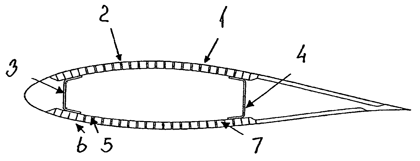
[0009]Thereby, the optimal material properties may be obtained by combining different types of strips, such as pultruded fibrous composite strips comprising different fibres, such as carbon fibres, glass fibres and / or natural fibres, wooden strips, composite strips formed as hollow tubes etc. Each of the types of strips are much simpler, and thus cheaper, to manufacture than to form a whole blade, and the strips may be joint by suitable methods, such as by injection of resin or by vacuum infusion of resin.
[0026]According to a preferred embodiment at least some of the pre-fabricated strips are made from a wooden material as wooden materials are low in costs an light weight, and the material properties of the wooden material may be completed to form the required blade material properties by combining with strips of other material types, such as fibrous composite materials. The wooden material may be strips of wood, which if necessary are glued together in the longitudinal direction of the blade.

Problems solved by technology

In order for the shell to bear a substantial part of the forces of the inner beam, the above discussed structures that are reinforced with wooden material require for larger dimensions of blades a thickness of the wooden layer that would increase the weight of the blade significantly, thus causing increased stresses to the blade.

Method used


Image

  • Wind turbine blade
  • Wind turbine blade
  • Wind turbine blade

Examples


Embodiment Construction

[0007]This object is obtained by a blade, which blade over a substantial longitudinal part comprises a layer along an outer periphery of the cross-section of the blade a blade, said layer constituted by a plurality of pre-fabricated strips arranged in a sequence along the outer periphery of the blade

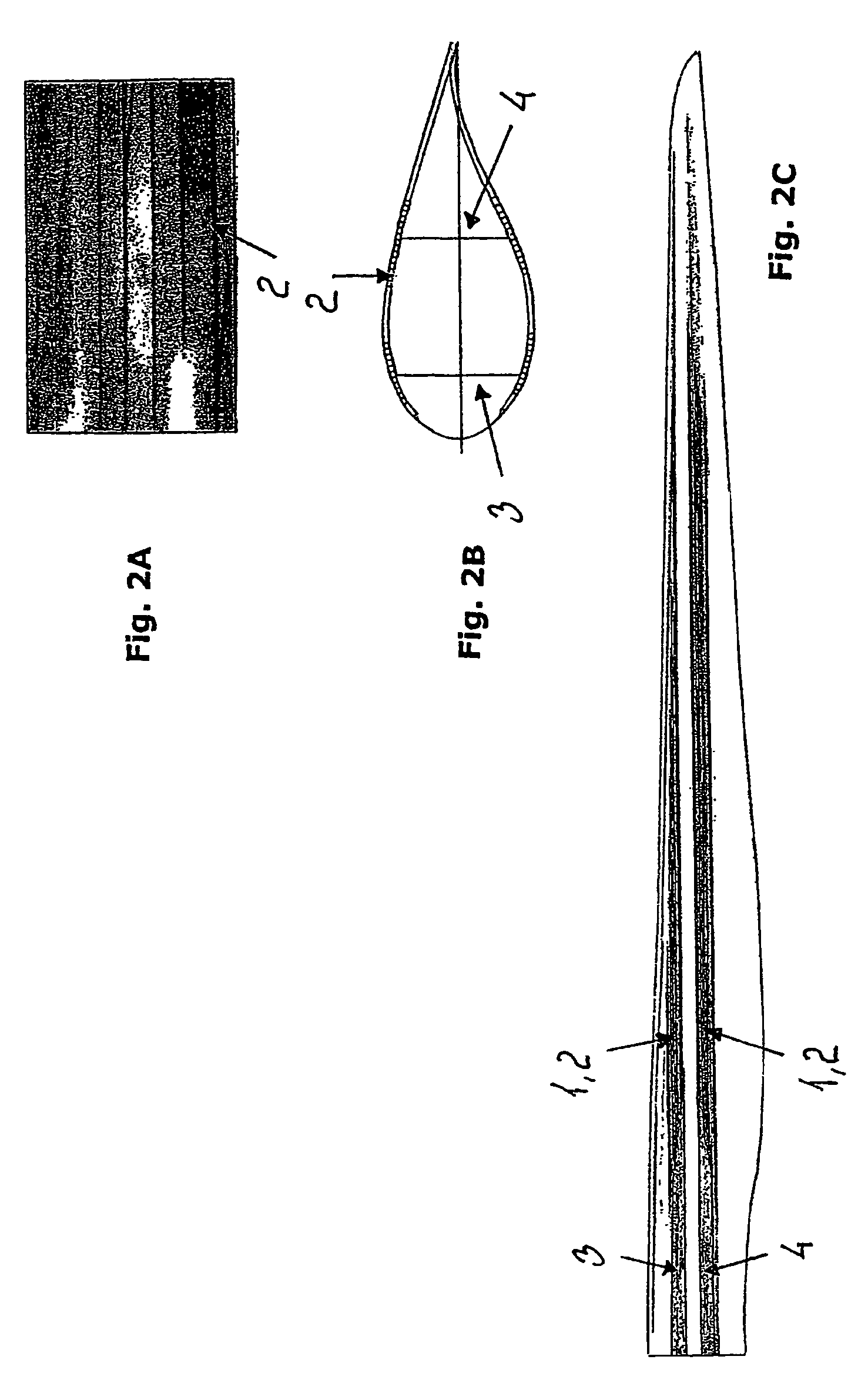
[0008]By the term “a substantial longitudinal part” is understood a part extending over at least a third of the total length of the blade from tip to hub, preferably over at least half of the total length of the blade. According to a preferred embodiment, 60–85% of the total length, such as about 70%, comprises such layer.

[0009]Thereby, the optimal material properties may be obtained by combining different types of strips, such as pultruded fibrous composite strips comprising different fibres, such as carbon fibres, glass fibres and / or natural fibres, wooden strips, composite strips formed as hollow tubes etc. Each of the types of strips are much simpler, and thus cheaper, to manufacture...


PUM

PropertyMeasurementUnit
Fractionaaaaaaaaaa
Fractionaaaaaaaaaa
Fractionaaaaaaaaaa

Abstract

The invention relates to a wind turbine blade comprising a number of pre-fabricated strips arranged in a sequence along the outer periphery. The strips consist of a fibrous composite material, preferably carbon fibres, and consist of a wooden material, preferably plywood or wooden fibres held in a cured resin. The advantage is that it is possible to manufacture blades for wind turbines which are very stiff and generally have a high strength, but which nevertheless are easy to manufacture and also is much cheaper to manufacture compared to conventional manufacturing techniques. The invention also relates to methods for manufacturing prefabricated strips and for manufacturing wind turbine blades.

Description

[0001]The present invention relates to a blade for wind turbines, in which blade the periphery layer of the cross section of the bladeBACKGROUND OF THE INVENTION[0002]Wind turbine blades are today manufactured comprising a bearing central inner beam, commonly of a hollow, square cross-section and made from a glass fibre and resin composite, surrounded with two shells forming the upper and the lower outer surface of the blade and determining the aerodynamic properties thereof.[0003]The shells may be of a single layer or at least along a part of the circumference be a sandwich construction comprising two parallel layers of glass fibres and resin having a space in between filled with e.g. a polyurethane foam. The use of a wooden material to reinforce the inner side of a single layer shell or to fill the space of a sandwich construction is well known.[0004]It is realised that the forces and torque increase steeply with the increasing length of blades and that the strength and stiffness ...

Claims


Application Information

Patent Timeline
IPC IPC(8): F01D5/12F01D5/14F03D80/00F03D1/06F03D3/06F03D17/00F03D80/30
CPCF03D1/065F03D1/0675F03D1/0683F05B2240/30Y02E10/721B29C70/443B29C70/52Y02E10/72Y02P70/50
Inventor GUNNESKOV, OLEBARLOW, NICHOLAS DUDLEYHANCOCK, MARKVRONSKY, TOMAS
Owner VESTAS WIND SYST AS
Learn More