Apparatus for multiple camera devices and method of operating same

a technology of multiple camera devices and apparatus, applied in the field of digital imaging, can solve the problems of negating the size advantage of electronic media, reducing the image quality, and difficulty in achieving the ever tightening demand of digital camera producers for smaller sizes, etc., and achieves the effects of high sensitivity, high resolution and enhanced imaging capability

Active Publication Date: 2007-04-03
INTELLECTUAL VENTURES II
View PDF24 Cites 433 Cited by
  • Summary
  • Abstract
  • Description
  • Claims
  • Application Information

AI Technical Summary

Benefits of technology

[0017]A sensor having two or more different arrays could advantageously have a different lens over each of the different arrays. Preferred lenses can employ a die coating, defused dye in the optical medium, a substantially uniform color filter or any other filtering technique through which light passes to the underlying array.
[0075]In some embodiments, the design and electrical operation of each sensor array is optimized for sensing the incident wavelengths of light to that sensor array. The use of multiple optical assemblies with individually optimized sensor arrays results is a compact camera capable of high resolution, high sensitivity and excellent color rendition.

Problems solved by technology

Although traditional component manufacturers continue to shrink the components to take advantage of the electronic media, it is difficult to achieve the ever tightening demand of digital camera producers for smaller sizes, lower costs and higher performance.
Several important issues remain, including: 1) the smaller the size of a digital camera (e.g., in cell phones), the poorer the image quality; 2) complex “lenses”, shutter and flash are still required for medium to higher quality imaging, thus negating much of the size advantage afforded by the electronic media; and 3) the cost advantage afforded by the electronic media is somewhat negated by the traditional complex and costly lens systems and other peripheral components.
These market needs can often be in conflict: higher performance often requires larger size, improved features can require higher cost as well as a larger size, and conversely, reduced cost and / or size can come at a penalty in performance and / or features.
As an example, consumers look for higher quality images from their cell phones, but are unwilling to accept the size or cost associated with putting stand-alone digital camera quality into their pocket sized phones.
These attributes (for example, increased number of pixels in the image sensor and optical zoom), although benefiting image quality and features, may adversely impact the camera size and cost.
In some cases, such as cell phones or other appliances where size and / or cost are critical, this approach to good image quality (high resolution and sensitivity) is not optimum.
In a manner similar to traditional enlargements, a degree of resolution is lost when performing this process.
Further, since digital cameras capture discrete input to form a picture rather than the ubiquitous process of film, the lost resolution is more pronounced.
These three color separation method have limitations as noted below.
The color filter array, such as the often used Bayer pattern, changes the incident color between adjacent pixels on the array and color crosstalk occurs that prevents accurate color rendition of the original image.
The color filter array may also have low and variable optical transmission that reduces received optical signal levels and creates pixel-to-pixel image non-uniformity.
The use of multiple imagers, with color separation methods such as a prism, provides accurate color rendition but the optical assembly is large and expensive.
Color separation methods within the pixel create crosstalk of colors and inaccurate color rendition.
Since multiple color charge collection and readout means are required in each pixel, pixel size reduction is limited.

Method used


Image

  • Apparatus for multiple camera devices and method of operating same
  • Apparatus for multiple camera devices and method of operating same
  • Apparatus for multiple camera devices and method of operating same

Examples


Embodiment Construction

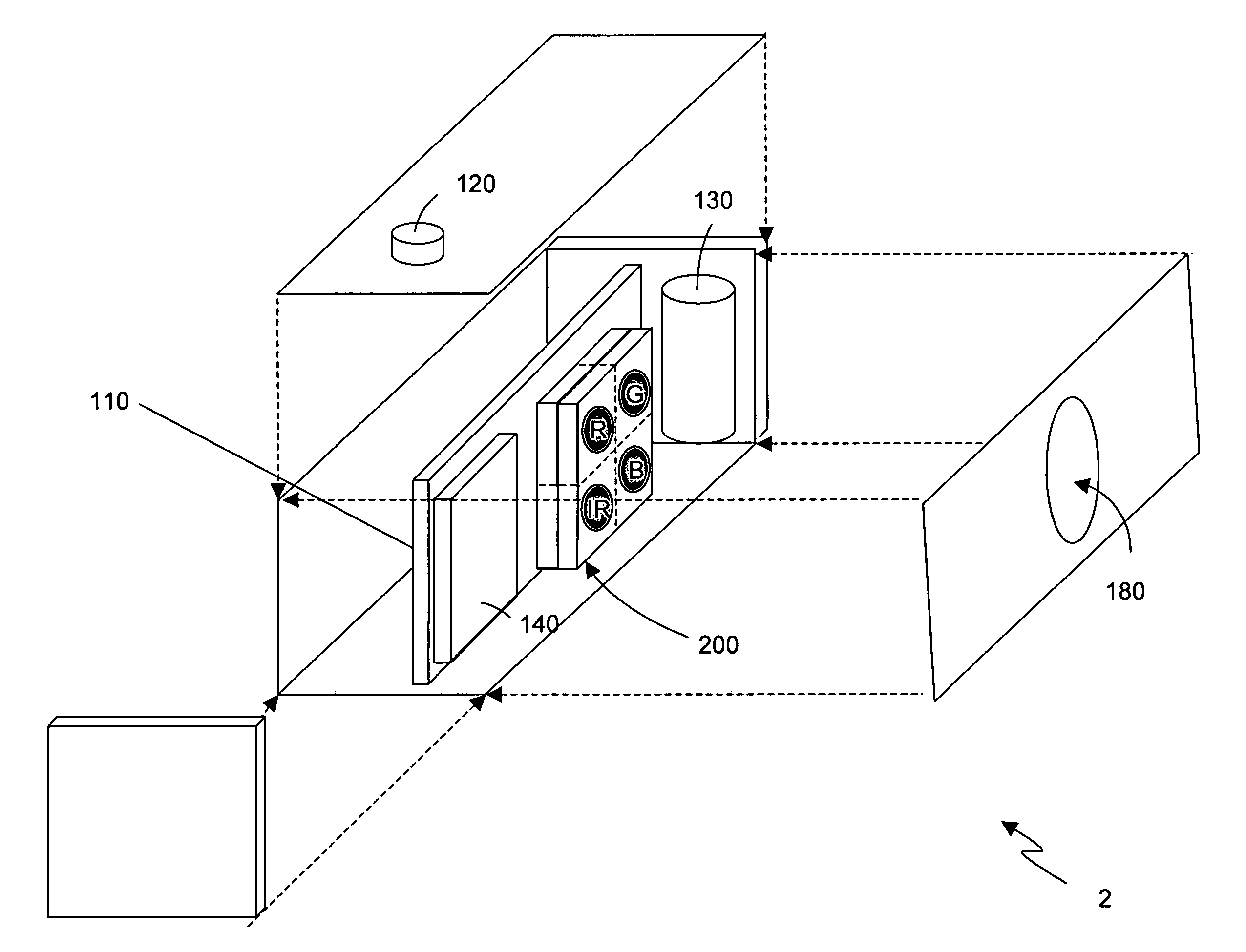
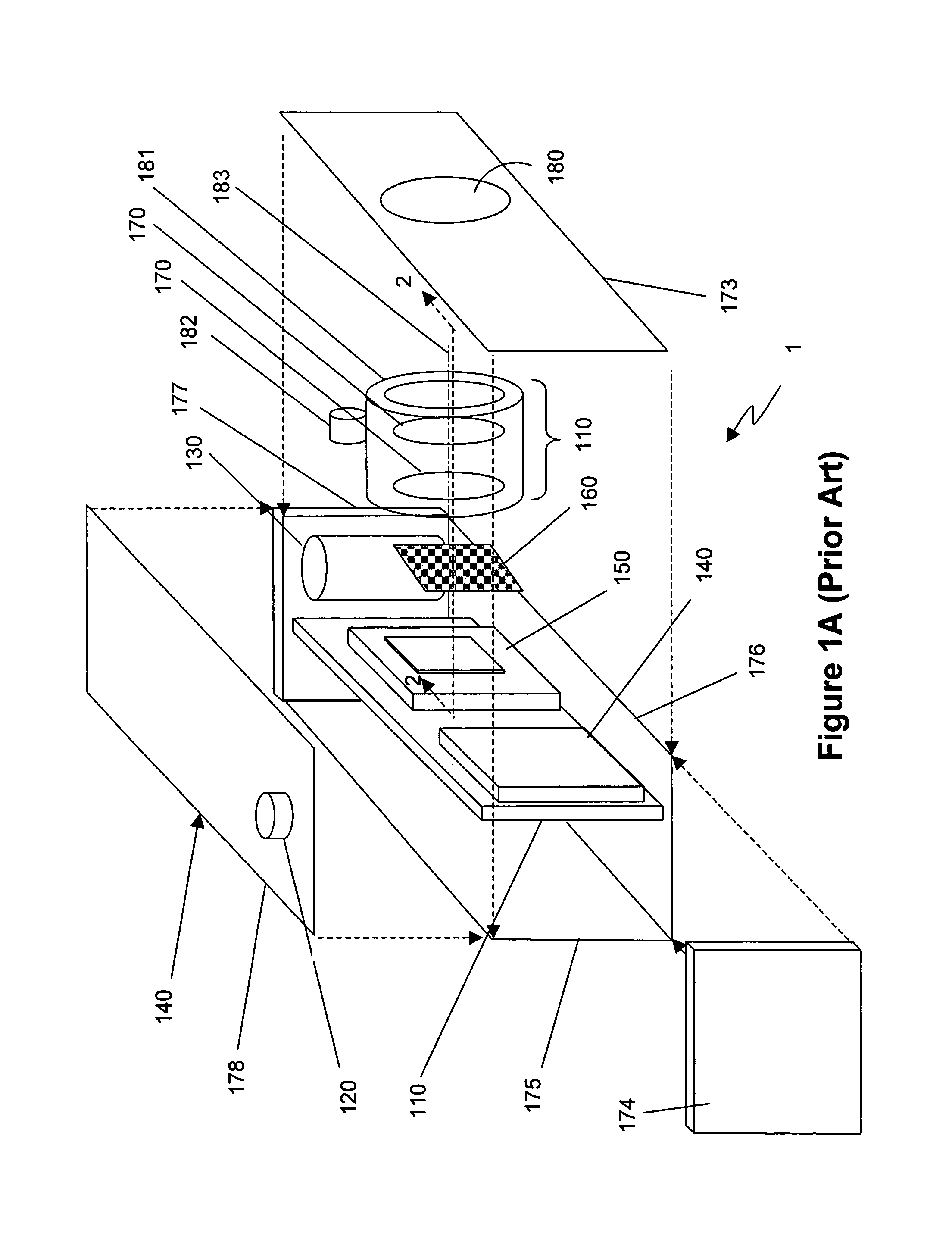
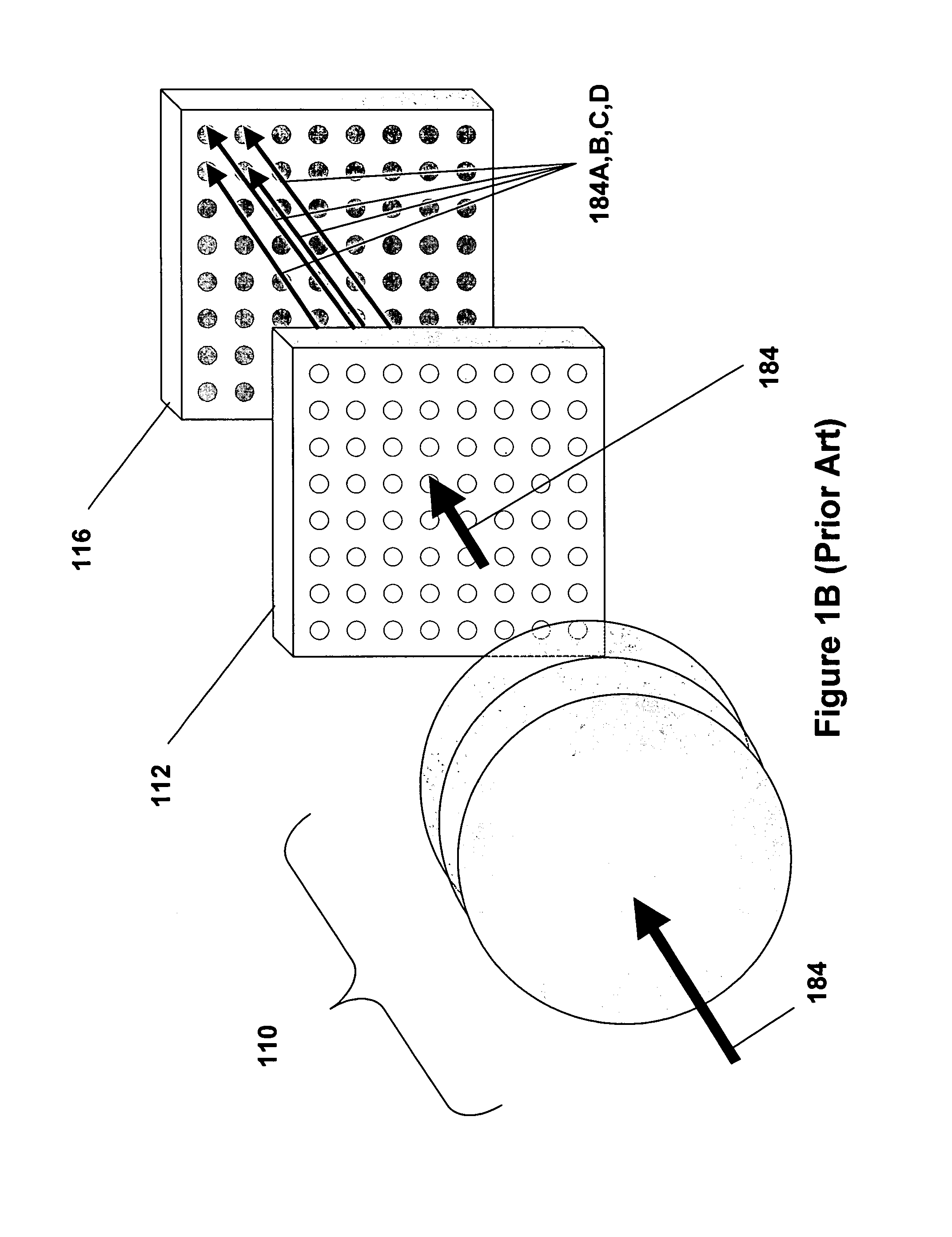
[0312]In FIG. 1A a prior art digital camera 1 generally includes the primary image capturing elements of an image sensor 150, a color filter sheet 160 and a series of lenses 170 (in a lens assembly). Additional electronic components typically include a circuit board 110, a peripheral user interface electronics 120 (here represented as a shutter button, but could also include display, settings, controls, etc), power supply 130, and electronic image storage media 140

[0313]The digital camera 1 further includes a housing (including housing portions 173, 174, 175, 176, 177 and 178) and a shutter assembly (not shown), which controls an aperture 180 and passage of light into the digital camera 1. A mechanical frame 181 is used to hold the various parts of the lens assembly together. The lens assembly includes the lenses 170 and one or more electro-mechanical devices 182 to move the lenses 170 along an axis 183. The mechanical frame 181 and the one or more electro-mechanical devices 182 may...


PUM


Abstract

There are many, many inventions described herein. In one aspect, what is disclosed is a digital camera including a plurality of arrays of photo detectors, including a first array of photo detectors to sample an intensity of light of a first wavelength and a second array of photo detectors to sample an intensity of light of a second wavelength. The digital camera further may also include a first lens disposed in an optical path of the first array of photo detectors, wherein the first lens includes a predetermined optical response to the light of the first wavelength, and a second lens disposed in with an optical path of the second array of photo detectors wherein the second lens includes a predetermined optical response to the light of the second wavelength. In addition, the digital camera may include signal processing circuitry, coupled to the first and second arrays of photo detectors, to generate a composite image using (i) data which is representative of the intensity of light sampled by the first array of photo detectors, and (ii) data which is representative of the intensity of light sampled by the second array of photo detectors; wherein the first array of photo detectors, the second array of photo detectors, and the signal processing circuitry are integrated on or in the same semiconductor substrate.

Description

RELATED APPLICATIONS [0001]This application is a divisional application of application Ser. No. 11 / 212,803 (still pending), filed Aug. 25, 2005. In addition, this application claims priority to: (1) U.S. Provisional Application Ser. No. 60 / 604,854, entitled “Solid State Camera”, filed Aug. 25, 2004; and (2) U.S. Provisional Application Ser. No. 60 / 695,946, entitled “Method and Apparatus for use in Camera and Systems Employing Same”, filed Jul. 1, 2005. The contents of the above-referenced Provisional and non-Provisional Applications are incorporated by reference herein in their entirety.FIELD OF THE INVENTION [0002]The field of the invention is digital imaging.BACKGROUND [0003]The recent technology transition from film to “electronic media” has spurred the rapid growth of the imaging industry with applications including still and video cameras, cell phones, other personal communications devices, surveillance equipment, automotive applications, computer based video communication and ...

Claims


Application Information

Patent Timeline
Patent Type & Authority Patents(United States)
IPC IPC(8): H04N3/14H04N5/225
CPCH04N5/228G02B3/0062G02B3/0075G02B7/04G02B9/12G02B13/0035G03B13/18H01L27/14618H01L27/14621H01L27/14625H01L27/14634H01L27/14645H01L27/1469H01L31/0232H04N5/2253H04N5/2254H04N5/2257H04N5/2353H04N5/332H04N5/335H04N5/3532H04N9/045H04N9/09H04N9/097G02B3/0031H04N2209/049G02B3/0043H01L2924/0002H01L31/02325H04N13/214H04N13/254H04N23/54H04N23/57H04N23/73H04N23/11H04N25/41H04N25/531H04N23/84H04N23/16H04N23/13H04N25/134H01L2924/00H04N23/69H04N23/40H04N25/00H04N5/265
Inventor OLSEN, RICHARD IANSATO, DARRYL L.MOLLER, BORDENVITOMIROV, OLIVERABRADY, JEFFREY A.GUNAWAN, FERRYOTEN, REMZISUN, FENG-QINGGATES, JAMES
Owner INTELLECTUAL VENTURES II
Why Eureka
Try Eureka