System and method for calibrating a fluorescence microscope

Inactive Publication Date: 2007-04-03
AVANTRA BIOSCI CORP
View PDF6 Cites 36 Cited by
  • Summary
  • Abstract
  • Description
  • Claims
  • Application Information

AI Technical Summary

Benefits of technology

[0021]In yet another embodiment, a control calibration chip is created in connection with the above technique. A control calibration chip is a target of robust mechanical and optical properties that is specifically associated with a particular fluorescence microscop...

Problems solved by technology

Unlike prior calibration techniques that attempted to provide a near-perfectly uniform fluorescent emitter target (which has proven impractical...

Method used


Image

  • System and method for calibrating a fluorescence microscope
  • System and method for calibrating a fluorescence microscope
  • System and method for calibrating a fluorescence microscope

Examples


Embodiment Construction

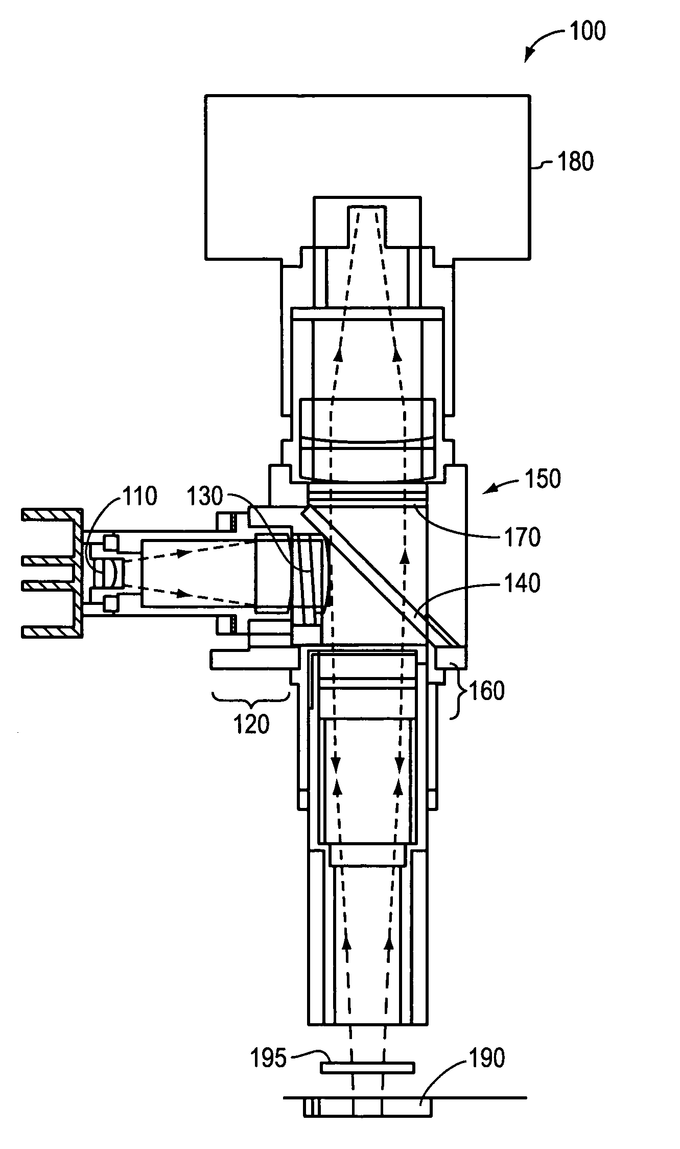
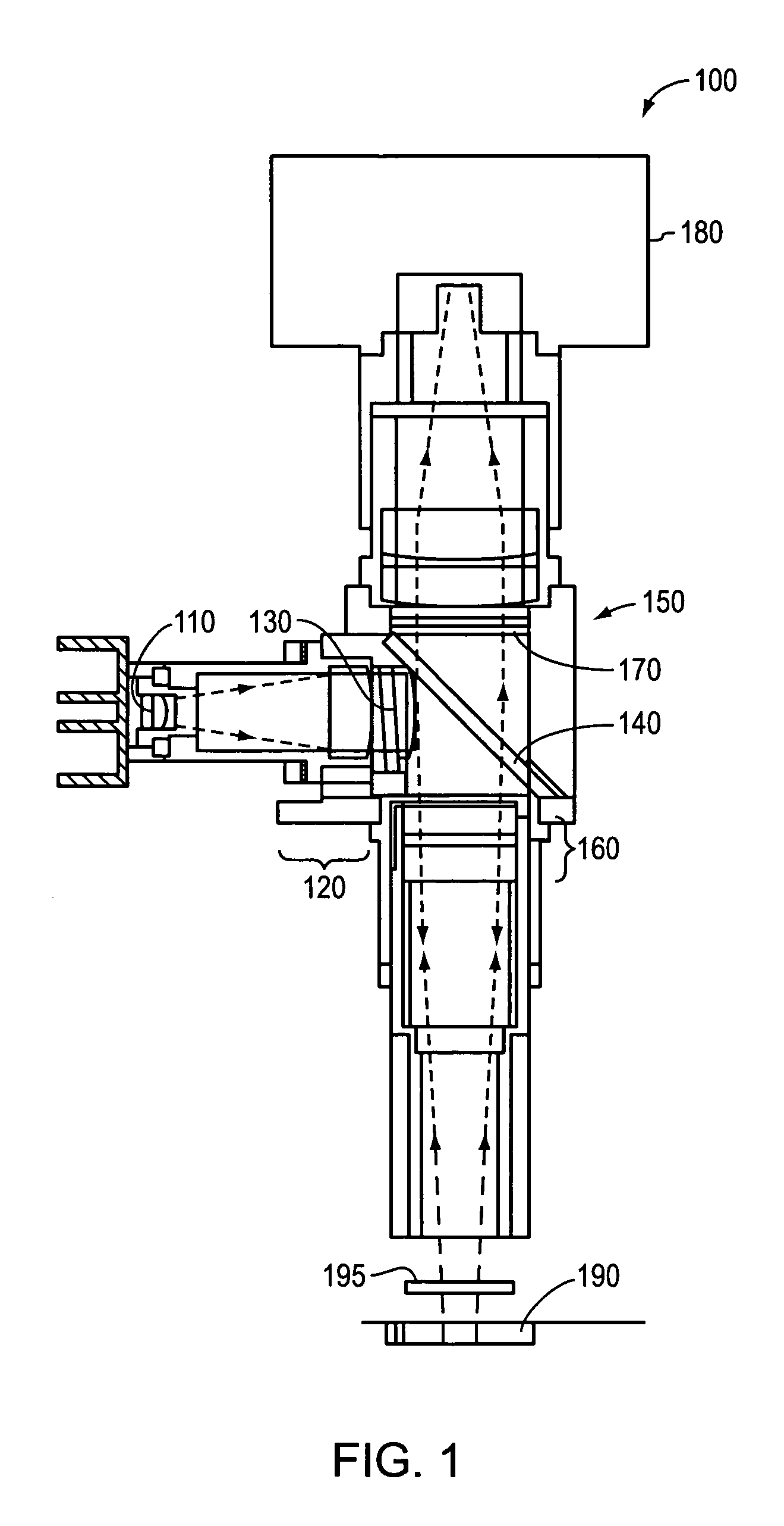
[0028]Throughout the description below, reference will be periodically made to structures depicted in FIG. 1. The reader is encouraged to refer to FIG. 1 when structures shown in FIG. 1 are discussed.

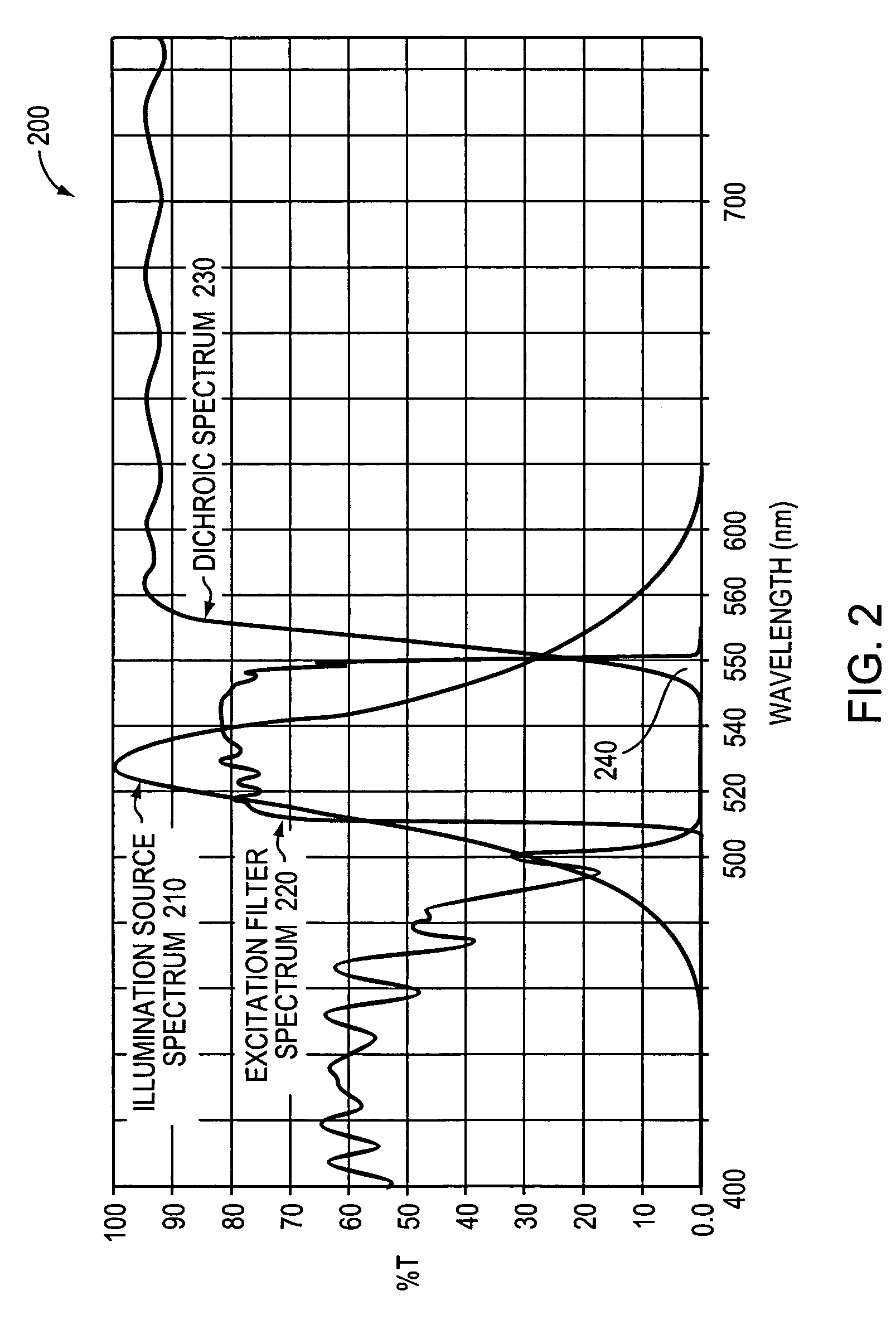
[0029]FIG. 2 is a graph depicting an exemplary illumination source spectrum 210, excitation filter spectrum 220 and dichroic spectrum 230 for an exemplary fluorescence microscope. Such spectrums are representative of one possible selection of components, for example, selection of a HQ535 / 50x Excitation filter and a Q565LP Dichroic, both available from Chroma Technology Corp. Typically, the illumination source 110 of a fluorescence microscope 100 produces multi-spectral light across a range of wavelengths. For example, FIG. 2 depicts an exemplary illumination source spectrum 210 spanning wavelengths from approximately 460 nanometer (nm) to 620 nm, with an intensity peak at approximately 530 nm. An excitation filter 130 is generally employed in the microscope to reduce the illumination li...


PUM


Abstract

A system and method are provided to calibrate fluorescence detection of a fluorescence microscope by using a near-perfectly uniform reflector as a target in combination with temporary removal of the microscope's emission filter. Excitation light is reflected from the near-perfectly uniform reflector back into the microscope's objective optical system and transmitted to a dichroic. A small fraction of the excitation light passes though the dichroic and is measured by a CCD camera or other appropriate measurement device. By measuring the intensity of the residual excitation light at a plurality of points in the field of view, variations in illumination intensity may be determined. Using this, fluorescence detection at different points in the field of view may be readily calibrated.

Description

BACKGROUND OF THE INVENTION[0001]1. Field of the Invention[0002]The present invention relates generally to microscope calibration and more particularly to the calibration of fluorescence detection across a field of view of a fluorescence microscope.[0003]2. Background Information[0004]The fluorescence microscope has become a valuable tool in biology and biomedical science, as well as in material science and other fields, due to its unique detection abilities. Such detection abilities are a result of the microscope's method of operation. When an organic or inorganic specimen (a target) is exposed to intense light (termed excitation light) it will generally emit light (termed emission light), in the physical phenomenon of fluorescence. Emission light typically is very faint, having only an intensity between a hundred thousandth and a millionth the intensity of the excitation light. A fluorescence microscope operates by separating the faint emission light from any reflected excitation ...

Claims


Application Information

Patent Timeline
IPC IPC(8): G01D18/00
CPCG01N21/274G01N21/6458G02B21/16G01N21/278
Inventor MONTAGU, JEAN
Owner AVANTRA BIOSCI CORP
Why Eureka
Try Eureka