Magnetic assembly for magnetically actuated control devices

a magnetic assembly and control device technology, applied in the direction of magnetic/electric field switches, electrical devices, contact, etc., can solve the problems of prior art proximity devices in control devices and physical monitoring systems, such as security alarms, unnecessary “false alarms” if not impossible to use proximity devices

Active Publication Date: 2007-04-03
EDMONSON JR MAHLON WILLIAM
View PDF11 Cites 13 Cited by
  • Summary
  • Abstract
  • Description
  • Claims
  • Application Information

AI Technical Summary

Benefits of technology

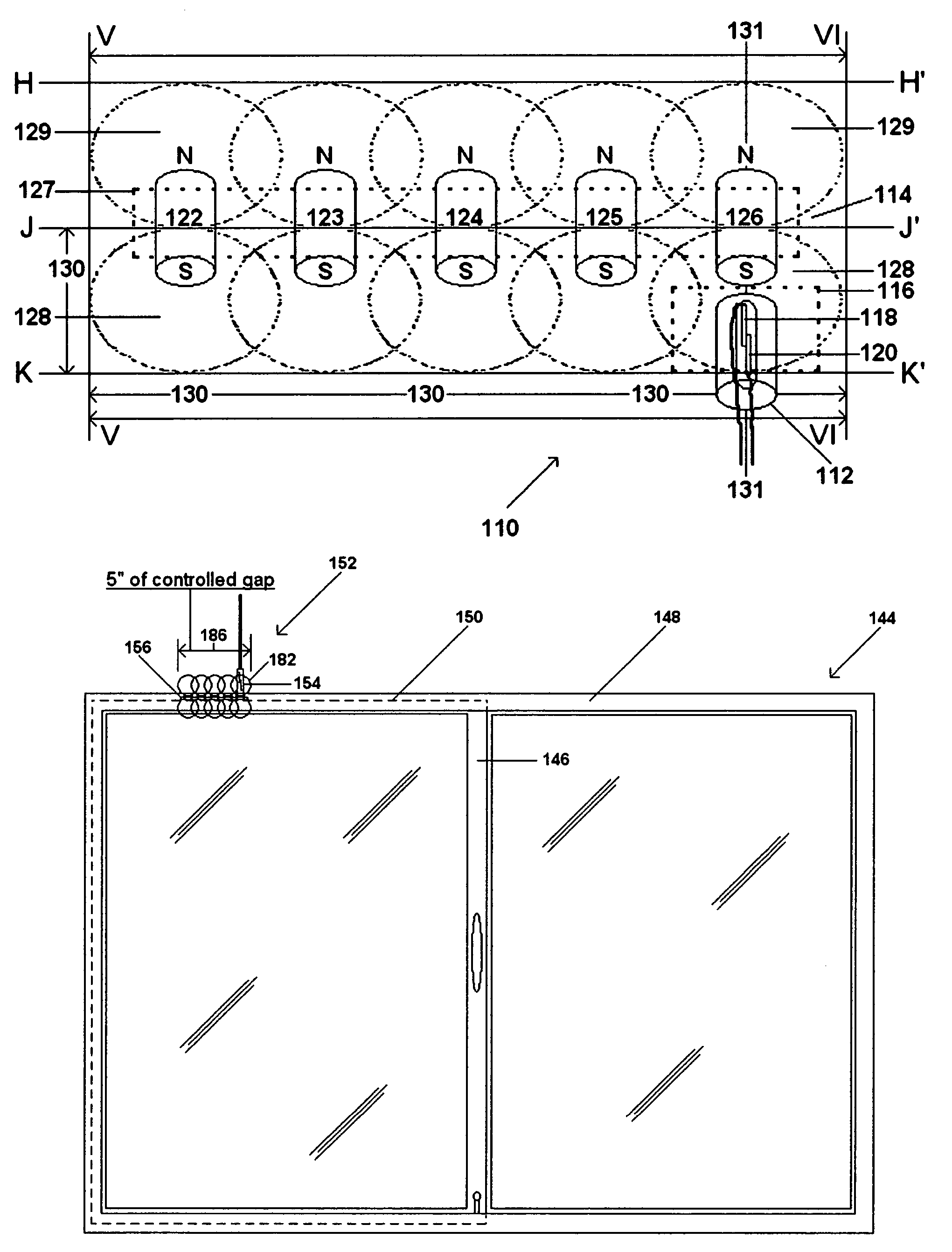
[0024]A magnetically actuated apparatus for use with magnetically controlled devices is provided. The apparatus is mountable to a movable closure member, having a fixed support member and a movable support member that are displaceable relative to one another. The apparatus comprises a sensor that is mounted to the fixed support member and a magnetic actuator mountable to the movable member. The sensor has a pair of contact members that are connectable to an electronic circuit. The contact members form a switch that is actuated by the magnetic actuator. The magnetic actuator preferably comprises a plurality of aligned, alike biasing magnets. The magnets have like magnetic poles that combine to form an effective magnetic actuation field that has a given magnitude and a given direction that is greater than the magnitude and direction of any one of the magnets. As an alternate embodiment, the magnetic actuator comprises an elongated magnetic bar that has unique specific polarization that may be used to actuate the sensor. In operation, the effective magnetic actuation field of the magnetic actuator increases the distance in which the movable member is displaceable relative to the fixed member without a change in the electric condition of the sensor.

Problems solved by technology

In view of the relatively small tolerances presently used and accepted in the industry for gap and break distances, a problem exists in the use of prior art proximity devices in control devices and physical monitoring systems, such a security alarms.
In view of the relatively small gap and break distances between the reed switch and the biasing magnet, slight movement of the biasing magnet relative to the reed switch could allow the reeds to be released, resulting in an unnecessary “false alarm”.
An example of this problem is found in the use of proximity switches in an overhead door for a garage, as one example.
This can create a problem with proximity devices that require careful alignment for operational stability.
Once the door shifts out of alignment, it is difficult, if not impossible to use the proximity device to set an alarm until the alignment is returned to at least the position when the proximity device was installed.
However, to the untrained eye of many customers, it is difficult to identify the problem.
To them the door is closed and secure, so something is wrong with the security alarm that was installed.
As a result, the customer requires the security alarm service to fix the problem at its own costs.
Even if the door is initially aligned when the alarm is set, problems with the security alarm still might occur.
Do to the overhead door being out of square, or possibly because a forklift has accidentally adjusted the door during the day, adverse pressure may create binding pressure that may cause the door to move after the door has been closed and secured.
The sudden and unanticipated movement of the door causes the biasing magnet to move out of alignment relative to the reed switch, thereby creating a condition in which the alarm may trigger.
In the security alarm industry, this is called “swinging” and can result in a false alarm.
Although the shift in a large overhead door is very gradual, the same problem of swinging can still occur.
For instance, it takes a long time for opening and closing pressure to shift the door segments of a commercial door.
But a drop in temperature can make the reeds contract.
For instance, in the example of the overhead door in which the security alarm is installed, the repeated movement or operation of the door can cause the door to move out of alignment relative to its initial position immediately after it was installed.
As such, a drop in temperature might cause both the magnet and reed switches metals to contract sufficiently to result in a false alarm activation.
As a result, the change in temperature may make it difficult for the magnetic field of the biasing magnet to bias one or both reeds sufficiently to operate the reed switch and in turn the security alarm.
As a result, the alarm will not be able to be set or will trigger a false alarm activation.
Another weather related problem is the wind.
Wind gusts might cause a garage door or window to move out of alignment after the alarm has been set.
Again, this slight movement can result in a false alarm.
If the alarm switch is on the edge but sets at the time of arming the biasing magnet could release the switch later resulting in a false alarm activation.
If the alarm sets with the opening in this position a false alarm activation could occur.
Accordingly, the precise alignment that is required to set and use a proximity device is a problem in the physical monitoring industry.
However, not all magnets or proximity switches are mounted perfectly to all surfaces.
This can lead to some hurried installations with some alarm contacts not being precisely aligned.
However, the magnetic field will shift out of alignment and require possible resetting by repeated service calls, which is a cost that is often paid for by the consumer.
Although perfect alignment is not an absolute requirement, if the biasing magnet is out of alignment by ½ to ¾ of an inch of its preferred position, problems with setting the alarm and weather will have an increased impact on the ability to set the alarm.
The contractions might cause the alignment of the reed switch relative to the biasing magnet to move even further.
Therefore, even if the reed switch is aligned sufficient to set the alarm, that condition may change at night when the temperature drops.
As the temperature drops, a false alarm might occur because the reed switch has moved out of alignment with the biasing magnet.
Because of the sensitivity of reed switches to slight or momentary movements and changes in temperatures, the reliability of proximity devices have been drawn into question.
False alarms produced by slight movement of the reed switch relative to the biasing magnet leads to unnecessary multiple police responses and as well as fines incurred by the customer.
In addition to the fines, the number of times a false alarm is triggered causes police and other law enforcement personnel to direct their attention away from other tasks as well as putting themselves and the public at risk during the response.
Furthermore, each time a false alarm occurs, a technician might be required to realign the relative position between the reed switch and the biasing magnet.
This becomes costly and reduces the ability to discern whether an alarm is triggered because of an intruder or because of some other reason.
Prior art solutions to the problem with proximity devices have been unsuccessful in resolving lateral shifting problems associated with magnetic reed switches.
The problem with lateral slide play cannot be addressed by the wide gap switches.
The problem resides in the physics of the poles of the magnet.
The other pole starts to cross the center of the reed, when the pole is near the center of the parallel reed it cannot maintain control of the reed.
This, combined with the fast speed of the alarm circuit, is where unnecessary false alarms are generated.
Holce teaches that by adjusting the distance of the biasing magnet, smaller magnets for a given separation makes the device less expensive to produce, more easily concealed from sight, and more difficult to detect.
However, Holce does not teach how to better control the sensitivity of the proximity devices through the use of an improved magnetic assembly that is relatively low in cost.
Also, Holce does not teach the use of an enhanced magnetic assembly that provides the flexibility to design the amount of gap or location of the break distance that is desired, beyond present industry standards.

Method used


Image

  • Magnetic assembly for magnetically actuated control devices
  • Magnetic assembly for magnetically actuated control devices
  • Magnetic assembly for magnetically actuated control devices

Examples


Embodiment Construction

[0087]FIG. 9 shows a magnetically actuatable apparatus 84 of the present invention for use with magnetically or electrically controlled devices or systems such as, for example, magnetically actuated reed switches and proximity devices that are used with physical monitoring or alarm systems. Apparatus 84 includes an enhanced, actuating magnet assembly or magnetic actuator 86 and a magnetically actuatable control device or sensor 88, also referred to in the security industry as a contact, which are operatively connectable to or associated with one another. The magnet actuator 86 comprises an assembly of multiple or a plurality of aligned, alike biasing magnetic fields (two shown) having overlapping magnetic fields. The magnetic actuator 86 is provided to magnetically actuate or to put into use at least a portion of sensor 88 using magnetism or an electro-magnetic field. In a preferred embodiment, two magnets 90 and 92 are shown to create the aligned, alike magnetic fields. It should b...


PUM


Abstract

A magnetically actuated apparatus, which enlarges, extends and makes continuous magnetic fields used by magnetically controlled devices, such as a magnetic reed switch for use in physical security monitoring systems is shown. Apparatus includes a sensor and a magnetic actuator for use with a movable closure member. The sensor is mounted into to a fixed support member that is arranged for displacement relative to a second movable support member. The sensor has a pair of contacts that are connectable to an electronic circuit. The contacts form a switch that is actuated by the magnetic actuator. The magnetic actuator comprises a unique elongated magnet with specific polarity or a plurality of aligned, alike permanent magnets that are mountable to the second support member. The aligned magnets have like magnetic fields that align one another and combine to form an effective magnetic actuation field that has a given magnitude and a given direction that is greater that the magnitude and direction than any one of the magnets. The elongated magnet has a specific pole for a given distance as its controlling means. The effective magnetic actuation field increases the distance in which the movable support member is displaceable relative to the fixed support member without changing the electric condition of the sensor. The present invention creates a magnetic apparatus, having a wider and controllable gap and break point distance not found in the present art.

Description

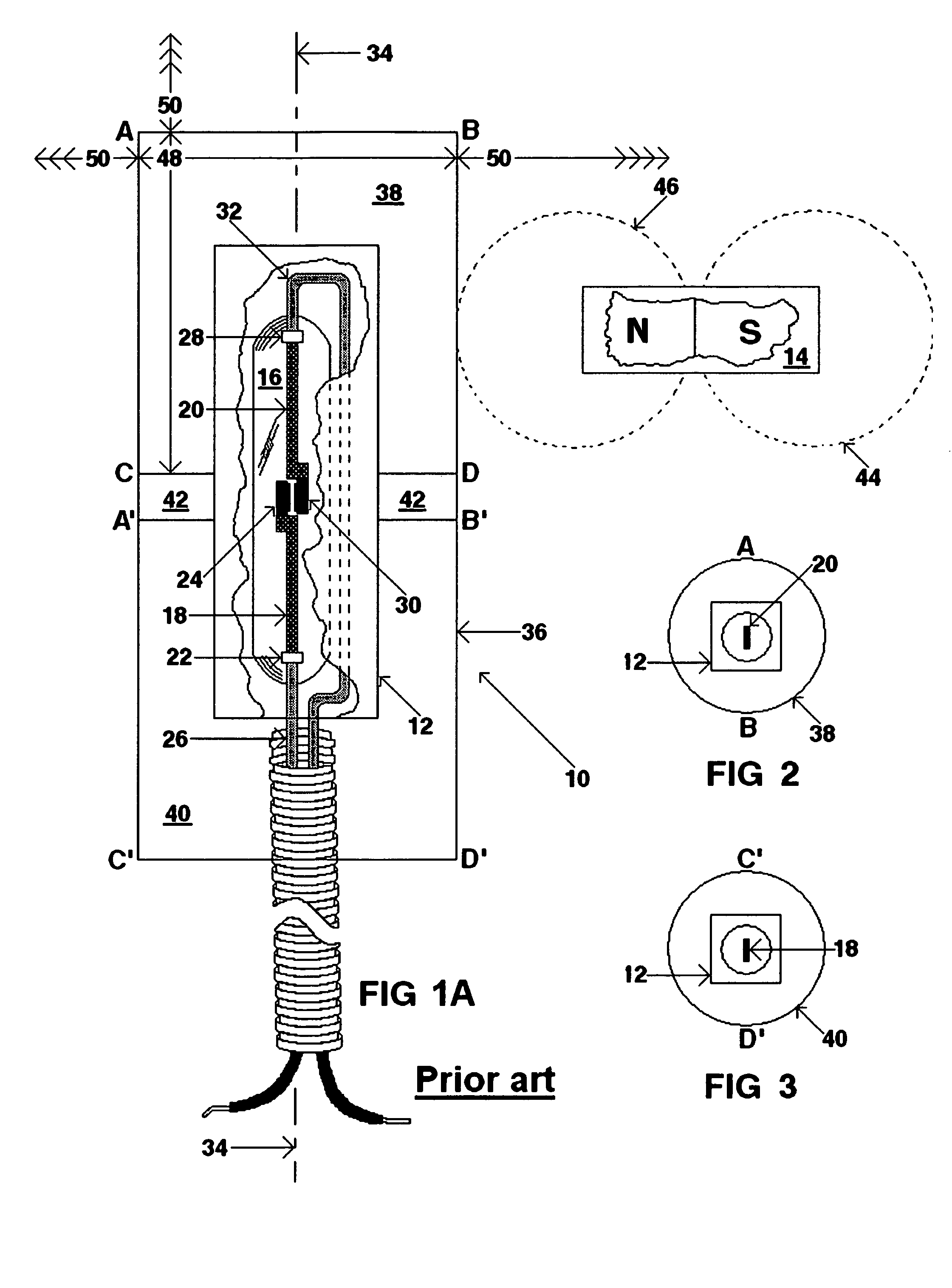
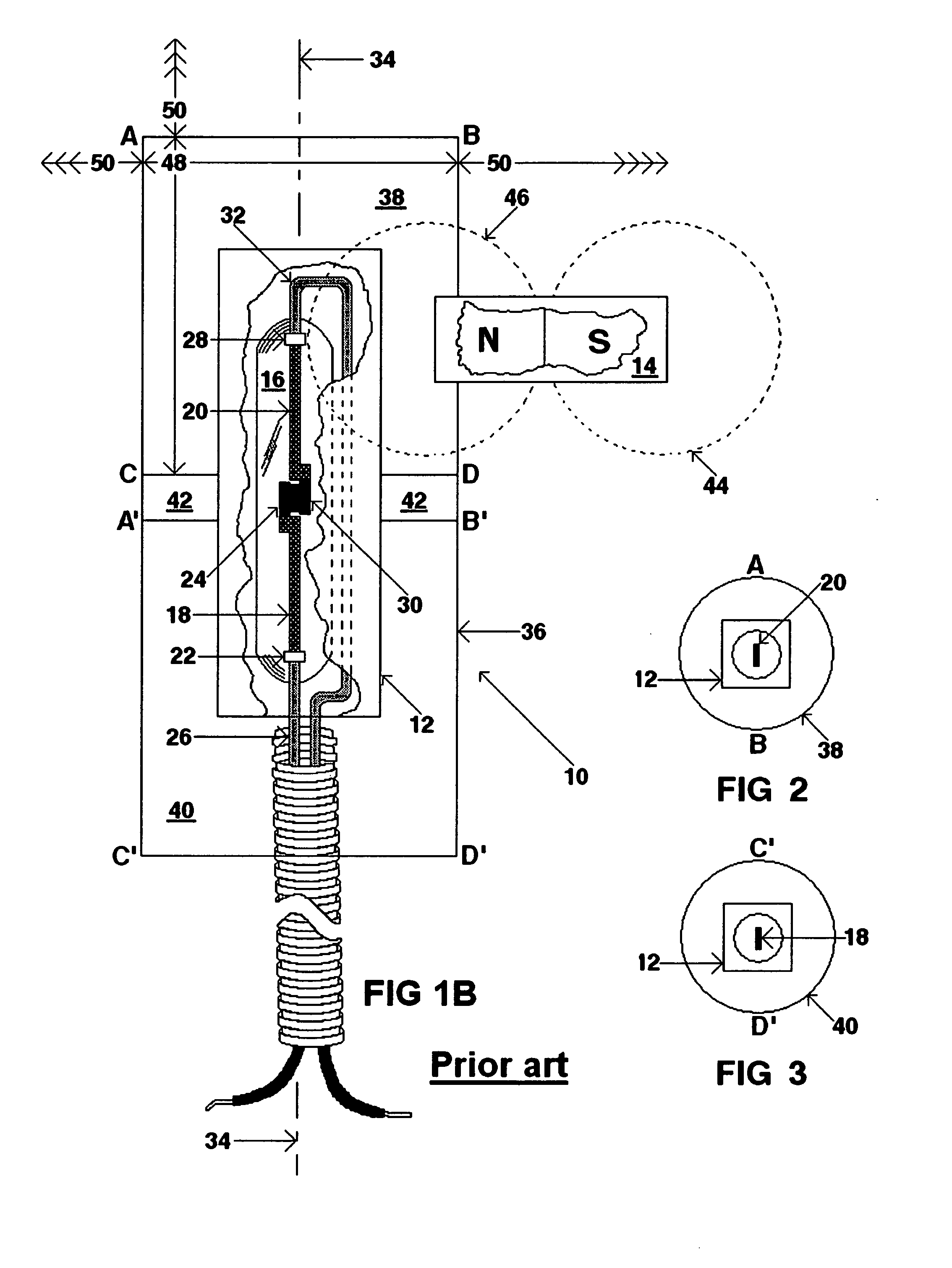
REFERENCE TO PRIOR APPLICATION[0001]This application claims the benefit of U.S. Provisional Application No. 60 / 455,061, filed on Mar. 14, 2003, entitled “Magnetic Assembly For Magnetically Actuated Control Devises,” in the name of Mahlon William Edmonson, Jr.FIELD OF THE INVENTION[0002]The present invention relates to magnetically actuated control devices. In particular, the present invention relates to an enhanced magnetic assembly for use with magnetically actuatable controlled devices, such as a magnetic reed switch used in a physical security monitoring system.BACKGROUND OF THE INVENTION[0003]Physical monitoring systems are well known in the art. Conventional monitoring systems typically comprise a reed switch that is electrically connected by wires to an electronic circuit, such as alarm or machinery control system. The reed switch generally comprises a cylindrical glass capsule containing a pair of electrical contacts disposed therein. Each contact is attached to a flexible or...

Claims


Application Information

Patent Timeline
Patent Type & Authority Patents(United States)
IPC IPC(8): H01H9/00H01H36/00
CPCH01H36/0013
Inventor EDMONSON, JR., MAHLON WILLIAM
Owner EDMONSON JR MAHLON WILLIAM
Why Eureka
Try Eureka