Dust bin and filter for robotic vacuum cleaner

Active Publication Date: 2007-04-10
HEALTHY GAIN INVESTMENTS
View PDF14 Cites 137 Cited by
  • Summary
  • Abstract
  • Description
  • Claims
  • Application Information

AI Technical Summary

Benefits of technology

[0004]The dust bin and filter assembly is desirably implemented such that the airflow is not perpendicular to the prefilter surface such that the kinetic energy of the air passing parallel to the filters keeps the filters free of clogs and reduces the frequency of cleaning.

Problems solved by technology

Designing a dust bin that can achieve an acceptable level of sustained performance to be usable with the lower initial suction force is the issue.

Method used


Image

  • Dust bin and filter for robotic vacuum cleaner
  • Dust bin and filter for robotic vacuum cleaner
  • Dust bin and filter for robotic vacuum cleaner

Examples


Embodiment Construction

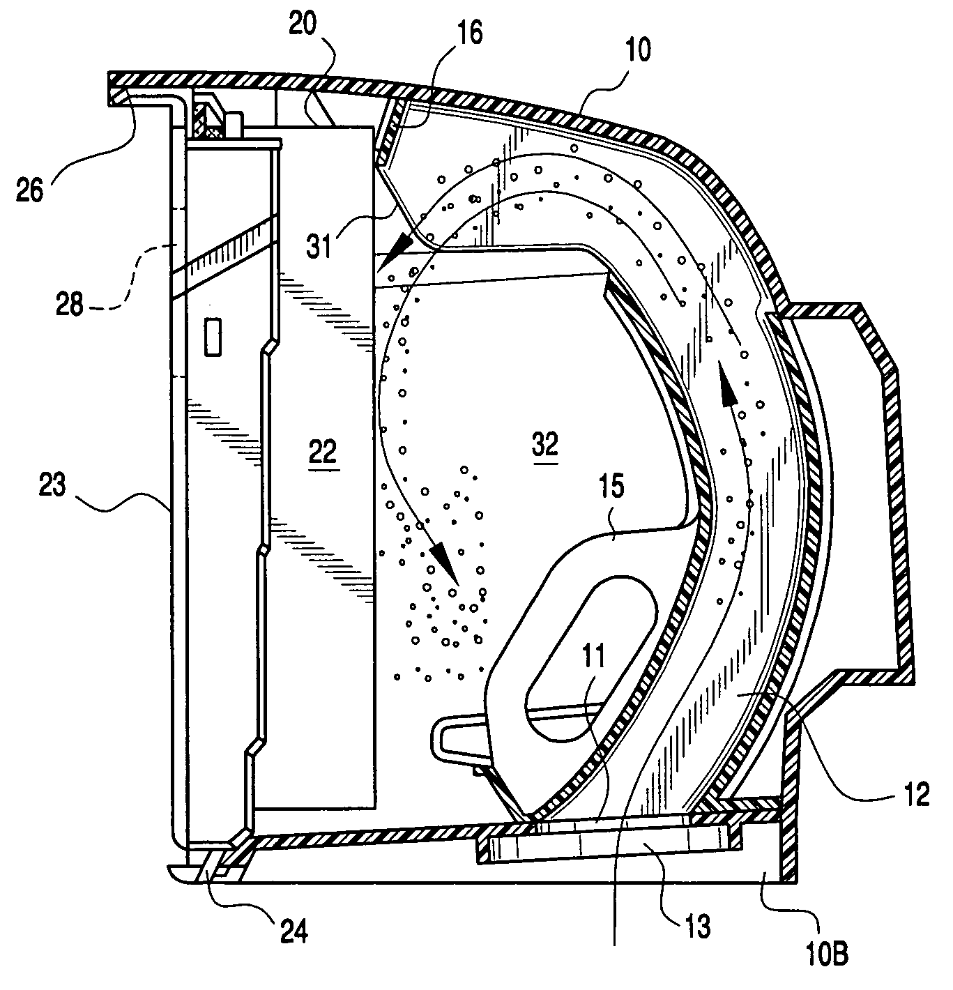
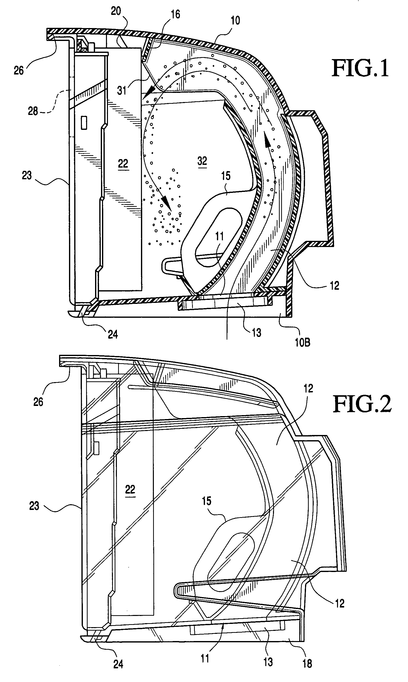
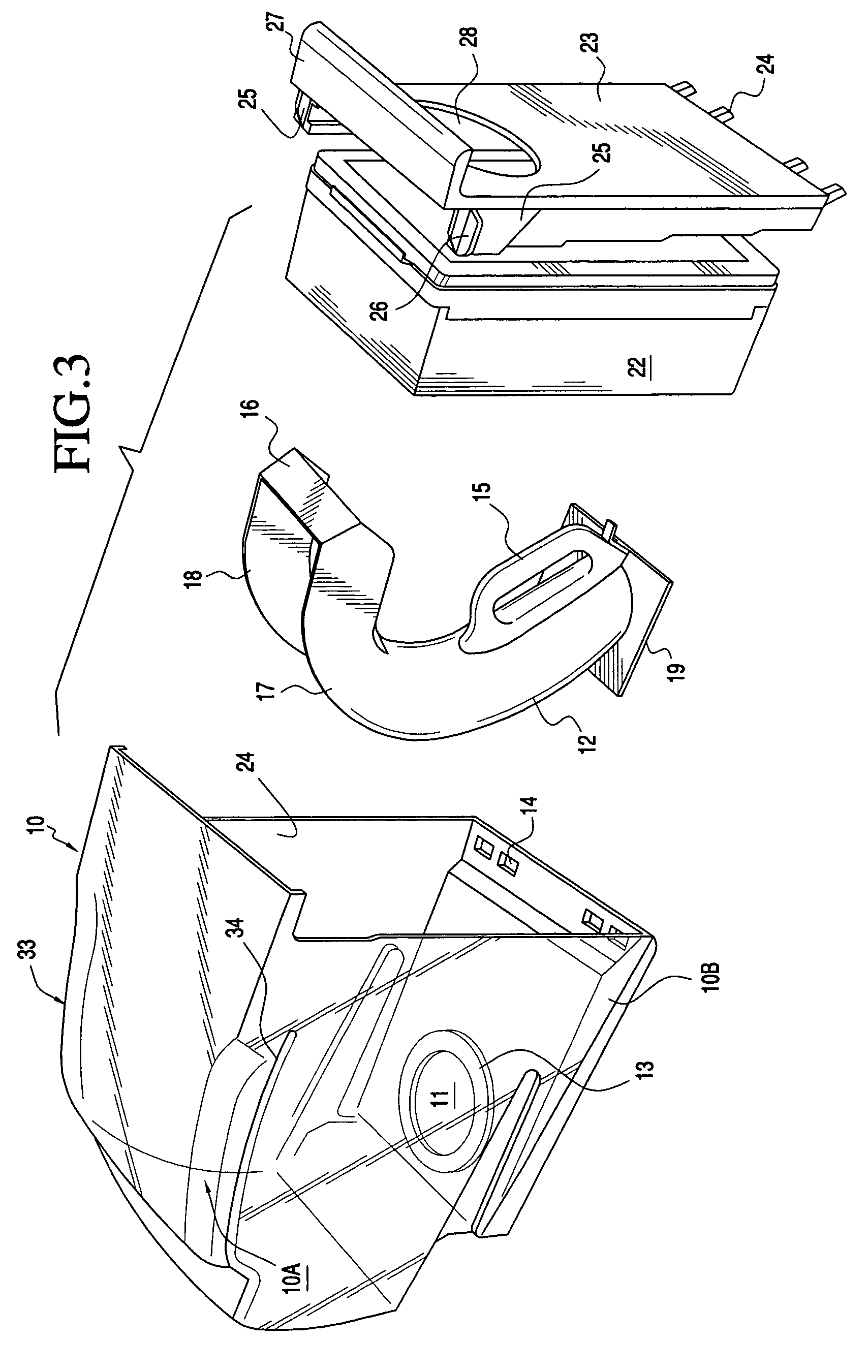
[0012]FIGS. 1–2 illustrate, respectively, the plan view and section view of the preferred embodiment of the dust bin as it sits within an autonomous vacuum cleaner. A container 10 is shown having a generally rectangular cross section, and may be made of acrylic or transparent / translucent material. An inlet 11 of the dust bin is formed on a recessed base 10b. The recessed base has an opening which includes a seal 13 which forms a connection to a passageway (not shown) connected to a vacuum cleaner nozzle. A source of vacuum is applied against outlet 28 when the dust bin 10 is located within its compartment of the autonomous vacuum cleaner, and a vacuum is drawn through outlet 28, filter 22, duct 12 and inlet 11.

[0013]Air laden with dirt enters the inlet 11, and travels through duct 12 which has an outlet 31 positioned in front of filter 22. The duct outlet 13 has a cross section plane which faces the filter assembly 22 at an angle. The dirt laden air exiting the duct 12 has a traject...


PUM

PropertyMeasurementUnit
vacuum pressureaaaaaaaaaa
angleaaaaaaaaaa
acute angleaaaaaaaaaa

Abstract

A detachable dust bin for a vacuum cleaner. A container is provided with a removable sidewall which has an outlet opening which is adapted to be coupled to a source of vacuum. The container includes an inlet for connecting to a passageway which is connected to a vacuum nozzle. A duct extends vertically from the inlet within the container, and then laterally toward the removable sidewall. A filter is supported along the removable sidewall having a front surface facing the outlet of the duct, and a rear surface facing the outlet opening in the removable sidewall. Dirt laden air is drawn through the filter, duct, and vacuum nozzle. Dirt is separated from the air and collected within the container.

Description

[0001]The present invention relates to vacuum cleaners in general, and in particular to autonomous vacuum cleaners. Specifically, a dust bin is provided for collecting dirt particles from a vacuum cleaner nozzle of an autonomous vacuum cleaner.[0002]Conventional vacuum cleaners remove dirt from floor surfaces by applying a vacuum through a nozzle to the floor surface. The dirt particles collected through the vacuum nozzle has usually been passed through a filter bag that removes particle material contained in the air stream from the air while maintaining the air flow through the vacuum system.[0003]Autonomous vacuum cleaners which navigate over a surface in accordance with a stored program, such as that shown in published U.S. patent application Ser. No. US2003 / 0060928A1, assigned to the Friendly Robotics Company, are battery operated and may generate a low level of suction force. Designing a dust bin that can achieve an acceptable level of sustained performance to be usable with th...

Claims


Application Information

Patent Timeline
Patent Type & Authority Patents(United States)
IPC IPC(8): B01D45/04A47L9/10B01D46/10A47L9/12A47L9/14A47L9/20B01D46/00B01D46/52B81C1/00H01L21/768
CPCA47L9/102A47L9/122A47L9/1409A47L9/20B01D46/008B01D46/10B01D46/52Y10S55/03A47L2201/00B01D46/88
Inventor WEGELIN, JACKSONSTEPHENS, RONDAMMAN, CHUCK
Owner HEALTHY GAIN INVESTMENTS
Why Eureka
Try Eureka