Electric machine with a circuit board for wiring lines of a winding system

a technology of winding system and circuit board, which is applied in the direction of windings, printed circuit manufacture, printed circuit non-printed electric components association, etc., can solve the problems of increasing complexity of printed circuit wiring on circuit board, increasing the complexity of assembly of electric machines, and increasing the cost of assembly. , to achieve the effect of simplifying the assembly of electric machines

Inactive Publication Date: 2007-04-10
SIEMENS AG
View PDF10 Cites 27 Cited by
  • Summary
  • Abstract
  • Description
  • Claims
  • Application Information

AI Technical Summary

Benefits of technology

[0009]According to another feature of the present invention, the circuit board may have plural feedthroughs for passage of winding leads which jut out radially from the winding system and are adapted for soldering to the feedthroughs. The term “winding lead” relates hereby to the respective ends of a winding, i.e. the beginning of a winding or the end of a winding. As a result of this construction, the windings can easily be interconnected, thereby further simplifying the assembly of the electric machine. In other words, the flexible circuit board can be mounted in a most simple manner to any one of the radial surface areas because the radially projecting winding leads can easily be routed through the feedthroughs, when the flexible circuit board is wrapped about the surface area. The winding leads can then be soldered to the circuit board in any suitable manner known to the artisan so as to interconnect the various coil windings of the winding system.
[0010]As an alternative, or in addition to the feedthroughs, it is also possible to provide the circuit board with plural soldering points for soldering the winding leads which jut out radially from the winding system. Thus, especially after attachment of the circuit board, the winding leads can be bent and appropriately placed upon the soldering points for subsequent soldering thereto. This approach also contributes to a space-saving construction of the electric machine according to the invention.

Problems solved by technology

Due to the circular configuration and the typical limitation of the diameter of the circuit board when attached to the radial dimension of the stator, the layout of the printed circuit wirings on the circuit board becomes progressively more complex, when the number of coil windings increases.
Moreover, as the winding leads cannot be easily fixed in axial direction, the assembly of the electric machine becomes even more complicated and expensive.

Method used


Image

  • Electric machine with a circuit board for wiring lines of a winding system
  • Electric machine with a circuit board for wiring lines of a winding system
  • Electric machine with a circuit board for wiring lines of a winding system

Examples


Embodiment Construction

[0019]Throughout all the Figures, same or corresponding elements are generally indicated by same reference numerals. These depicted embodiments are to be understood as illustrative of the invention and not as limiting in any way. It should also be understood that the drawings are not necessarily to scale and that the embodiments are sometimes illustrated by graphic symbols, phantom lines, diagrammatic representations and fragmentary views. In certain instances, details which are not necessary for an understanding of the present invention or which render other details difficult to perceive may have been omitted.

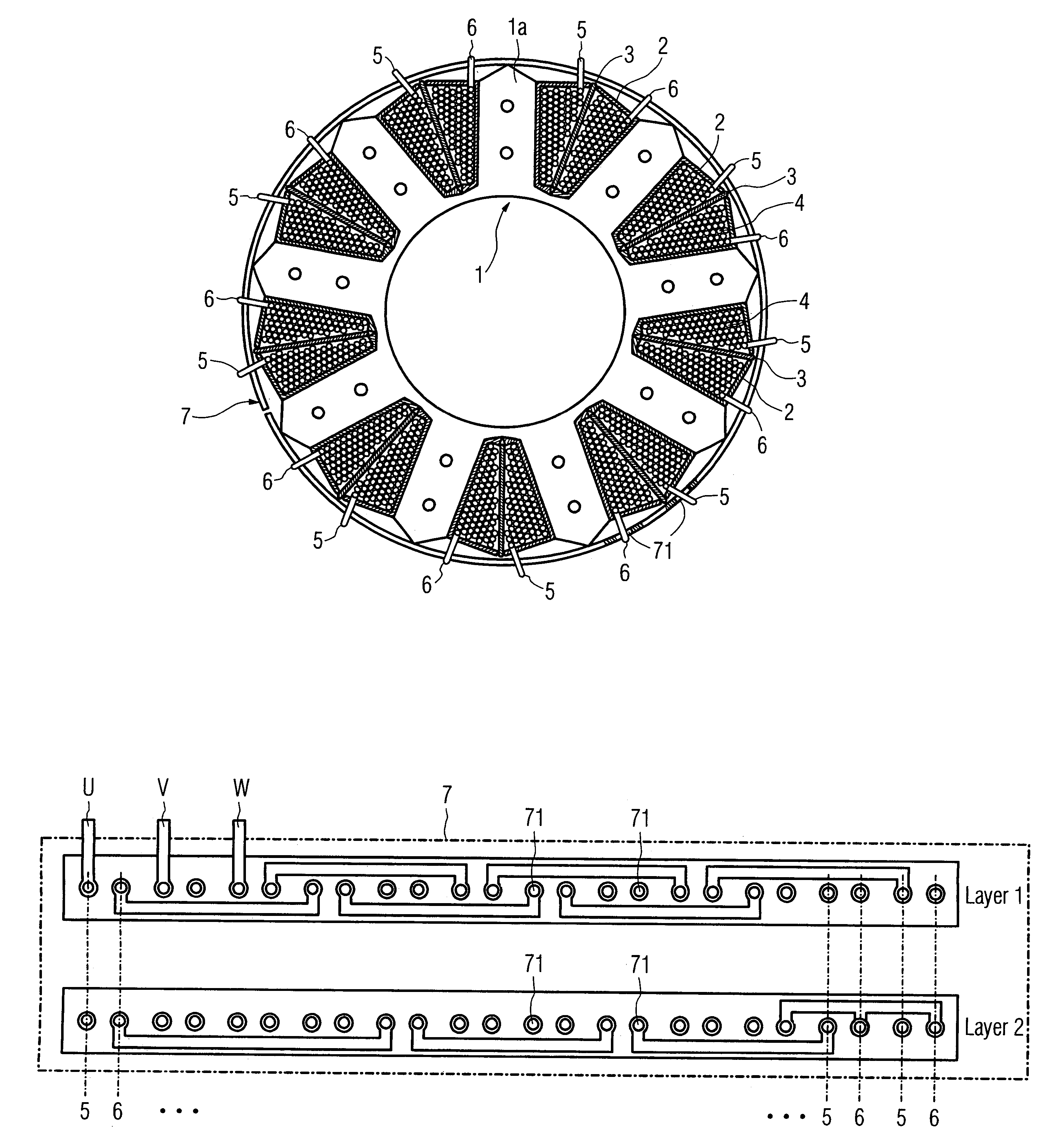
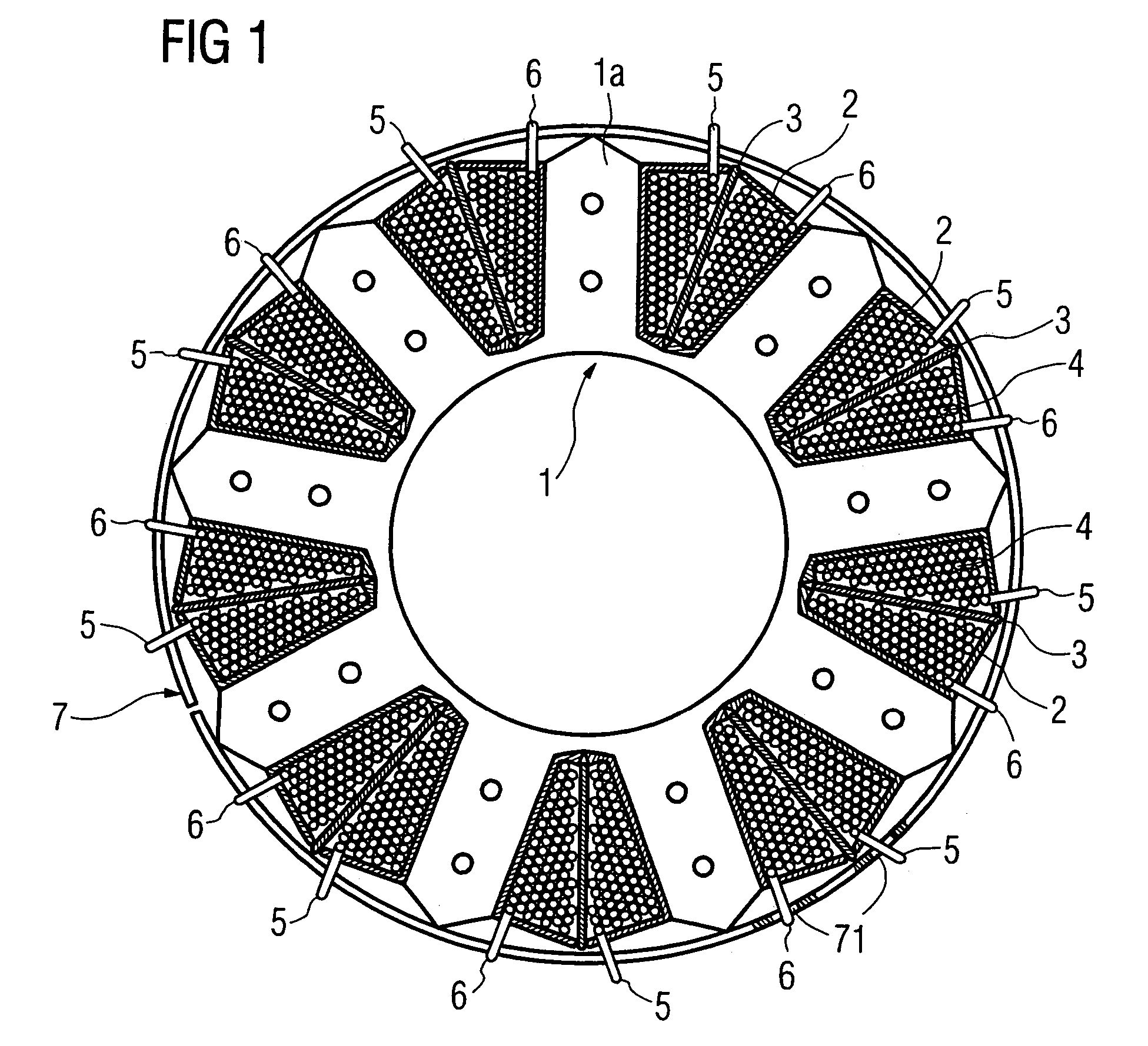
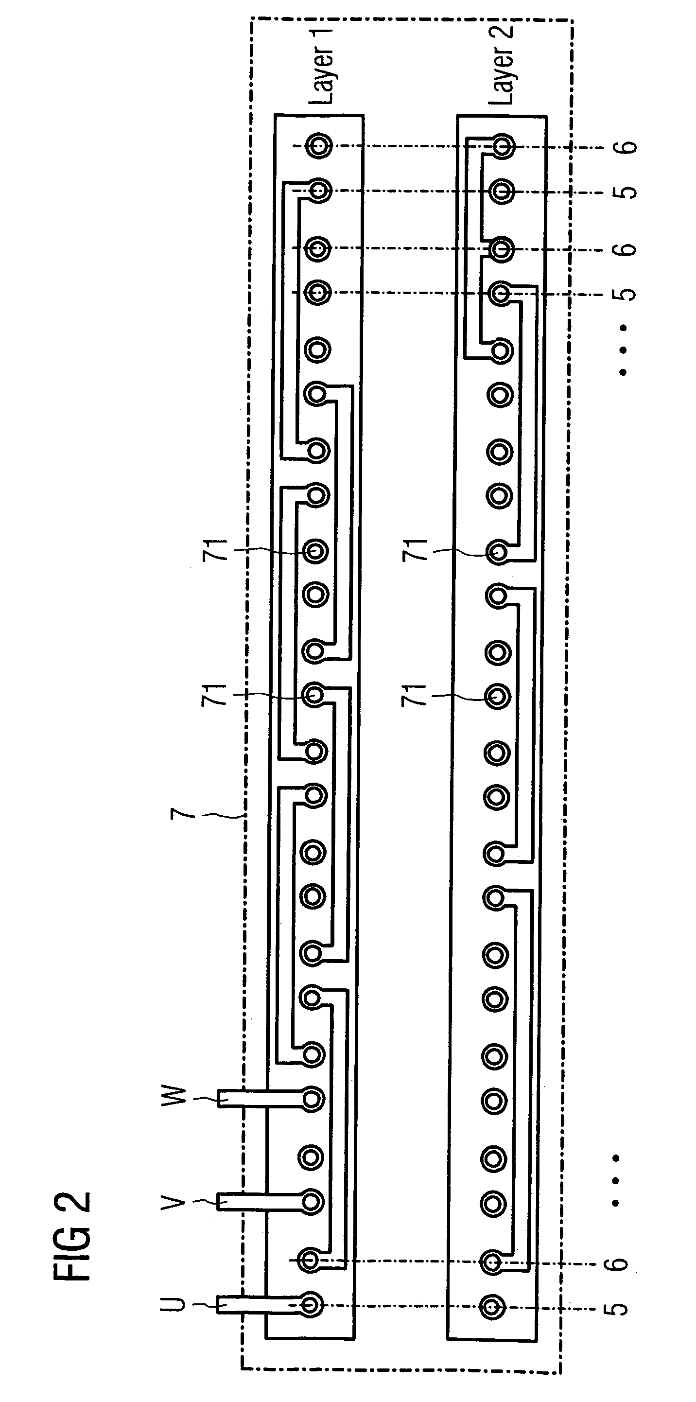
[0020]Turning now to the drawing, and in particular to FIG. 1, there is shown a sectional view of an electric machine having incorporated the subject matter of the present invention. The electric machine includes a stator, generally designated by reference numeral 1 and constructed in tooth coil technology or exciter coil technology. In the nonlimiting example of FIG. 1, the s...


PUM


Abstract

An electric machine includes a stator having a plurality of slots and a winding system having windings placed in the slots. The windings of the winding system are interconnected by at least one flexible circuit board which is constructed for attachment to a radial surface area of the stator and for connection to the windings.

Description

CROSS-REFERENCES TO RELATED APPLICATIONS[0001]This application claims the priority of European Patent Application, Serial No. 04005467.8, filed Mar. 8, 2004, pursuant to 35 U.S.C. 119(a)–(d), the subject matter of which is hereby incorporated by reference.BACKGROUND OF THE INVENTION[0002]The present invention relates, in general, to an electric machine, and more particularly to a device for connecting winding leads of a winding system of an electric machine.[0003]Nothing in the following discussion of the state of the art is to be construed as an admission of prior art.[0004]Electric machines typically include a stator in the form of a stator core of stacked laminations. The stator core can have a star-shaped configuration and has slots for placement of at least one winding system constructed through tooth coil technology or exciter coil technology, involving a plurality of coil bobbins placed in the radial slots of the stator core, with each of the coil bobbins including an exciter...

Claims


Application Information

Patent Timeline
Patent Type & Authority Patents(United States)
IPC IPC(8): H02K3/50H02K11/00H02K3/52H05K1/18H05K3/34
CPCH02K3/522H05K1/189H05K3/3447
Inventor ECKERT, RAINERPAWELLEK, JURGEN
Owner SIEMENS AG
Why Eureka
Try Eureka