Position-control stage system

a technology of position control and stage system, which is applied in the direction of magnetic circuit rotating parts, mechanical energy handling, shape/form/construction, etc., can solve the problems of large or bulky stage system in contour or outside diameter, and remains a major challenge to make the position control stage system much smaller in construction

Active Publication Date: 2007-04-10
NIPPON THOMPSON
View PDF10 Cites 14 Cited by
  • Summary
  • Abstract
  • Description
  • Claims
  • Application Information

AI Technical Summary

Benefits of technology

[0008]The present invention, therefore, has as its primary object to overcome the subject as described just above and more particular to provide a position-control stage system with an onboard direct-drive linear motor in which an armature assembly fits into a circular recess cut in a stationary bed in a way approaching as closer as possible to an outside circular surface of an outer race of a rolling-contact bearing to ensure much space to install the armature assembly on the bed, even with as small as allowed in diametral dimension, and correspondingly a turntable fits over the outer race of the rolling-contact bearing to render the circular linear motor compact or slim in construction, thereby making the stage system itself as smaller as possible in diameter, even with high in propulsion and efficient in operating performances including high-speed traveling, high response, high-precision position-control, and so on.
[0014]The position-control stage system of the present invention constructed as stated earlier is allowed to shrink in diameter as smaller as possible, compared with the prior position-control stage system disclosed in the commonly assigned Japanese Patent Laid-Open No. 2004-72960. Even though the bed is constructed as small as allowed in dimension while the turntable is also made as compact as possible to shrink the position-control stage system itself down to any permitted mark, the present invention succeeds in disposing the armature assembly and the field magnet on the bed and the turntable, respectively, which are enough to provide the permanent-magnet motor, which is high in propulsion to drive the turntable in circular direction and efficient in operating performances including high-speed turning, high response, high-precision position-control, and so on.

Problems solved by technology

This circular construction of the armature windings and the magnet segments results in rendering the stage systems large or bulky in contour or in outside diameter thereof.
Thus, it remains a major challenge to make the position-control stage system much smaller in construction, even with enhancing propulsion to turn a turntable.

Method used


Image

  • Position-control stage system
  • Position-control stage system
  • Position-control stage system

Examples


Embodiment Construction

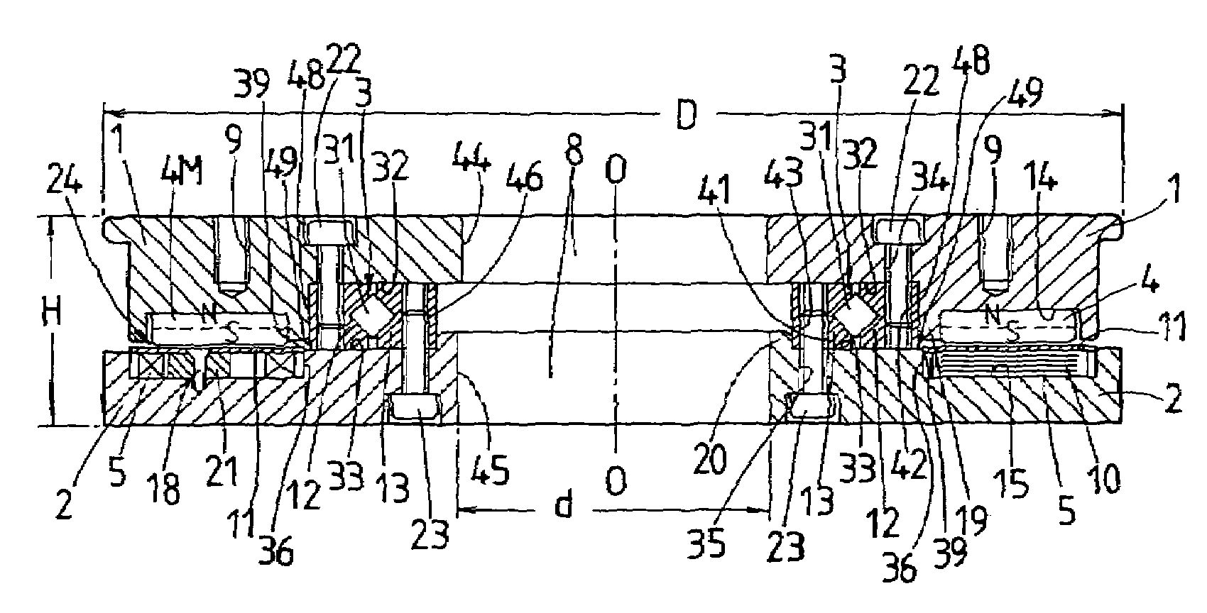
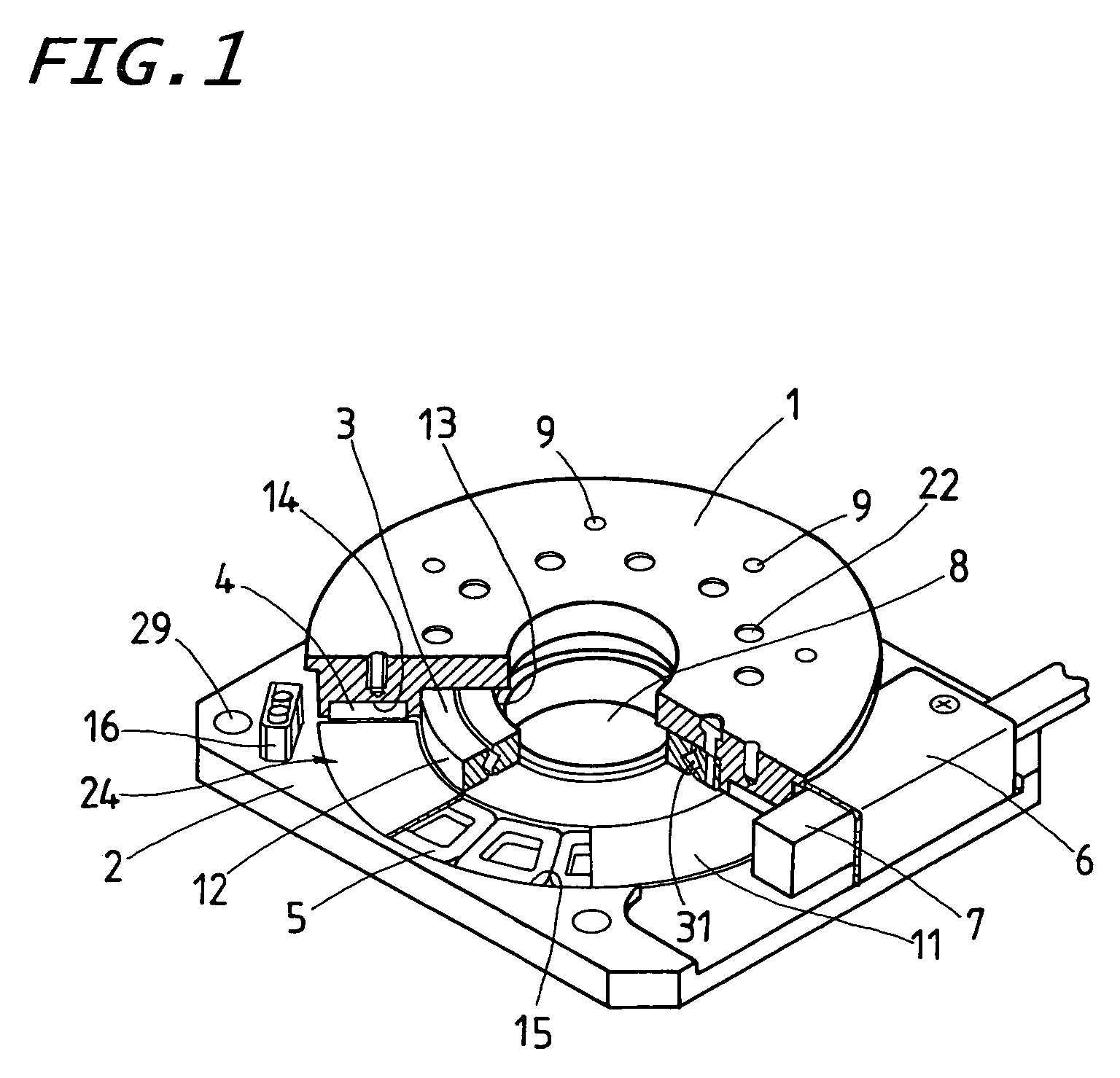
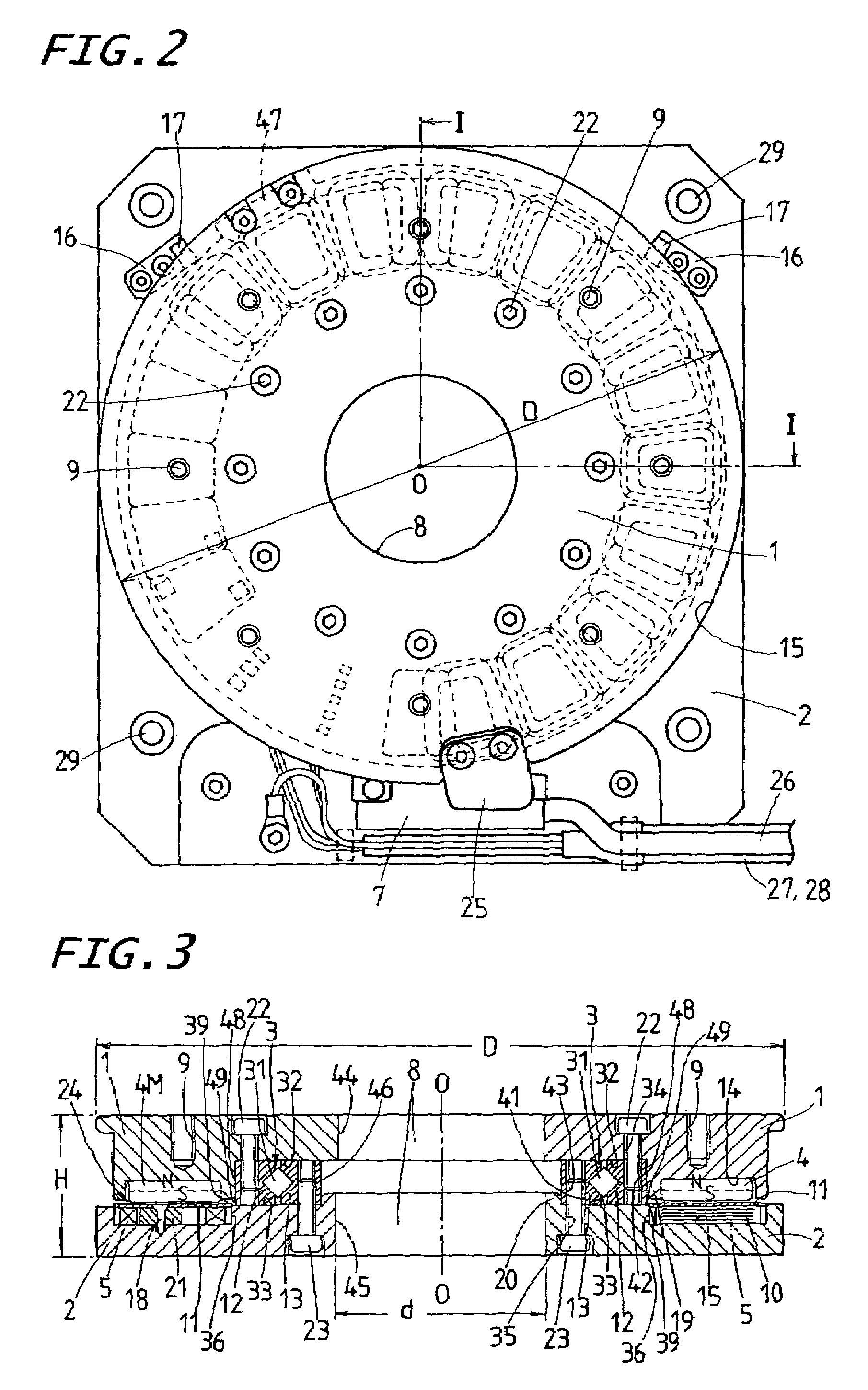
[0026]The position-control stage system of the present invention is designed to serve well for machinery including semiconductor manufacturing equipment, assembling machines, measuring instruments, testing instruments, position-control table system, sliding table system, and so on, which are expected to operate in any controlled atmosphere as in, for example clean rooms, testing / experimental laboratories, and the like.

[0027]Preferred embodiments of a position-control stage system according to the present invention will be explained hereinafter in detail with reference to the accompanying drawings. The position-control stage system of the present invention, besides the constructional features common to the position-control stage system disclosed in the commonly assigned Japanese Patent Laid-Open No. 2004-72960, is envisaged further developing the existing position-control stage system as disclosed previously. The position-control stage system of the present invention is made smaller ...


PUM


Abstract

A position-control stage system is disclosed, which may ensure much space to install the armature assembly on the bed, even with small in dimension. Correspondingly, the position-control stage system itself is made high in propulsion and efficient in operating performances including high-speed traveling, high response, high-precision position-control, and so on, even with compact or slim in construction. Armature windings to provide an armature assembly are made of three-phase coreless windings wound in annular flat configuration, and disposed on the bed radially outside of a rolling-contact bearing in a way closely adjacent to the bearing. Magnets to provide a field magnet array are each made in a segment, and disposed on the turntable in opposition to the armature windings in a way alternating in polarity circularly on a desired circular surface.

Description

FIELD OF THE INVENTION[0001]The present invention relates to a position-control stage system with onboard a motor comprising armature windings and field magnets, which has been extensively used in fields as diverse as semiconductor manufacturing equipments, assembling machines, precise testing machines, measuring / inspection equipments, and so on.BACKGROUND OF THE INVENTION[0002]In recent years, position-control stage systems have been needed to be compact or slim in construction and able to operate with high speed and high response to make sure of high speed movement and accurate position control so as to meet anticipated design specifications in extensively increased fields including semiconductor industries, and the like. A typical version of the prior position-control stage systems has an onboard permanent-magnet motor comprised of a primary side of armature windings and a secondary side of field magnets.[0003]An example of the prior position-control stage systems as stated earli...

Claims


Application Information

Patent Timeline
Patent Type & Authority Patents(United States)
IPC IPC(8): H02K21/24H01L21/027H02K5/16H02K7/08H02K7/14H02K21/12H02K41/00H02K41/02H02K41/03
CPCH02K7/088H02K7/14H02K21/24
Inventor IDA, EIJI
Owner NIPPON THOMPSON
Why Eureka
Try Eureka