Power factor improving circuit

a technology of power factor and improving circuit, which is applied in the direction of electric variable regulation, process and machine control, instruments, etc., can solve the problems of complicated circuit adjustment and difficulty in stably controlling the power factor improving circuit, and achieve the effect of simplifying the structure, reducing the number of circuit parts, and reducing the cost of power factor

Active Publication Date: 2007-04-10
SANKEN ELECTRIC CO LTD
View PDF6 Cites 62 Cited by
  • Summary
  • Abstract
  • Description
  • Claims
  • Application Information

AI Technical Summary

Benefits of technology

[0012]The present invention provides an inexpensive power factor improving circuit in which the number of parts of the circuit is reduced to simplify its structure, it is easy to adjust the circuit, the number of negative feedback loops is reduced so that the circuit can stably be controlled, and the number of wires can also be reduced.

Problems solved by technology

For this reason, the number of parts of the power factor improving circuit is large, and it is difficult to stably control the power factor improving circuit.
Since the number of parts of the power factor improving circuit is large, adjustment of the circuit becomes complicated.

Method used


Image

  • Power factor improving circuit
  • Power factor improving circuit
  • Power factor improving circuit

Examples


first embodiment

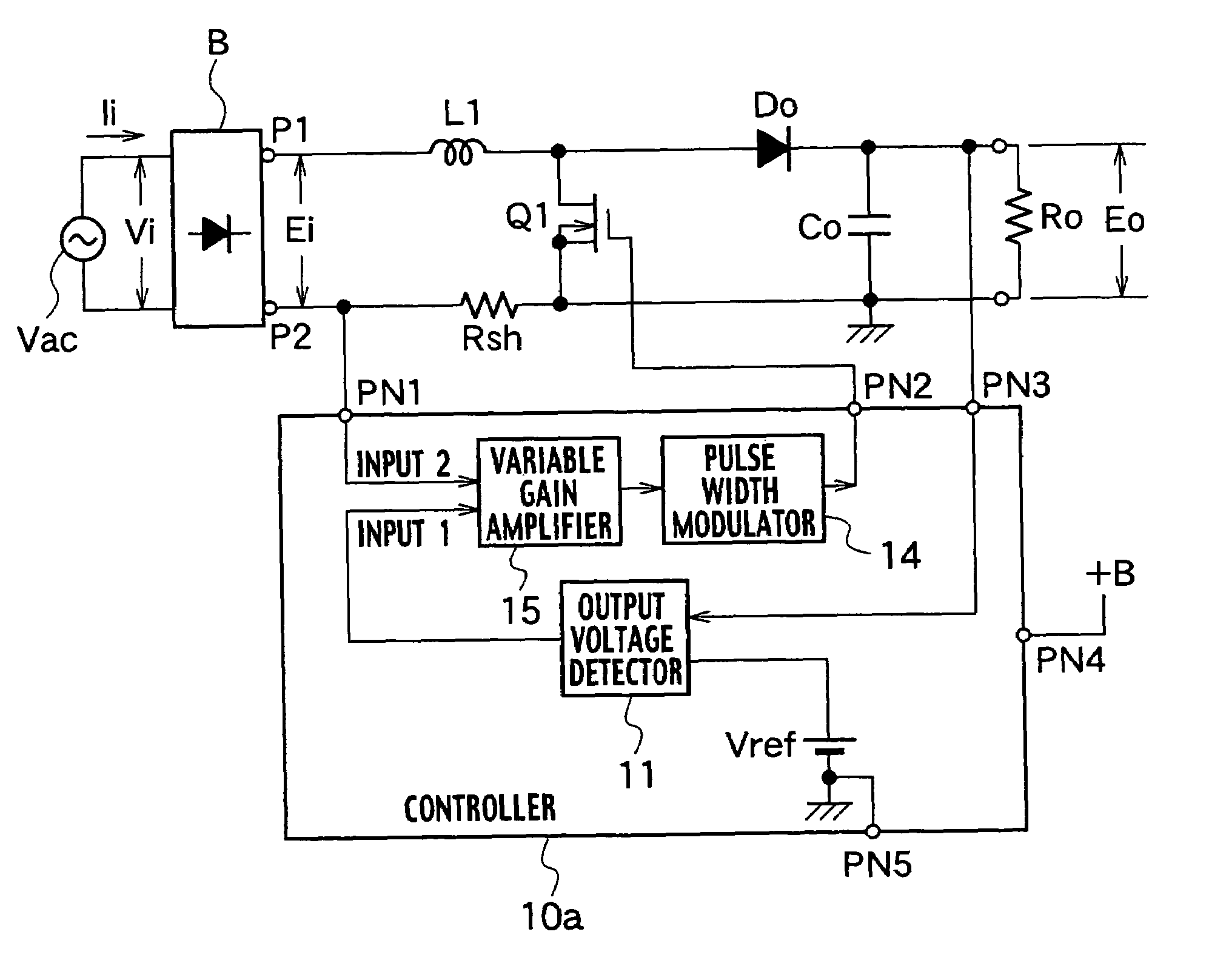
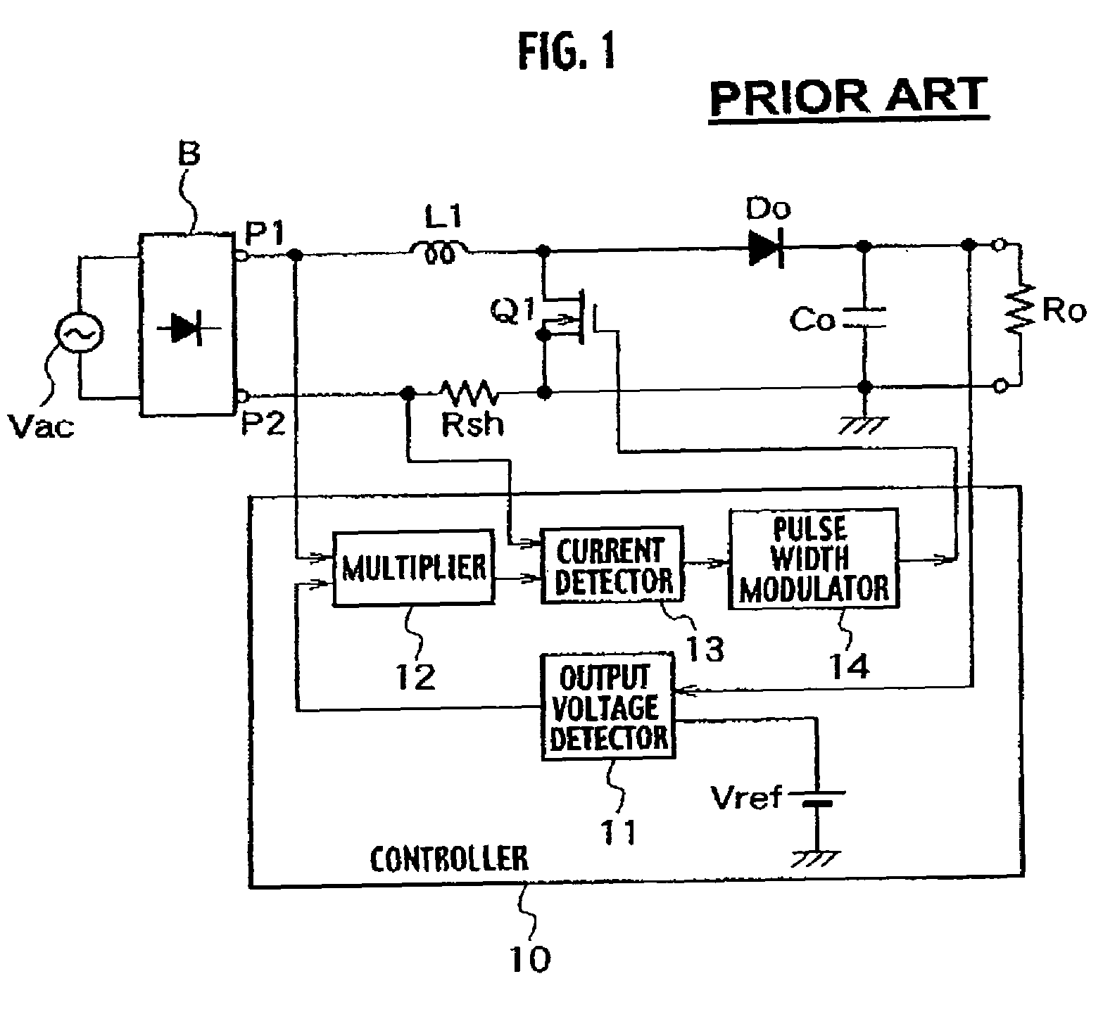
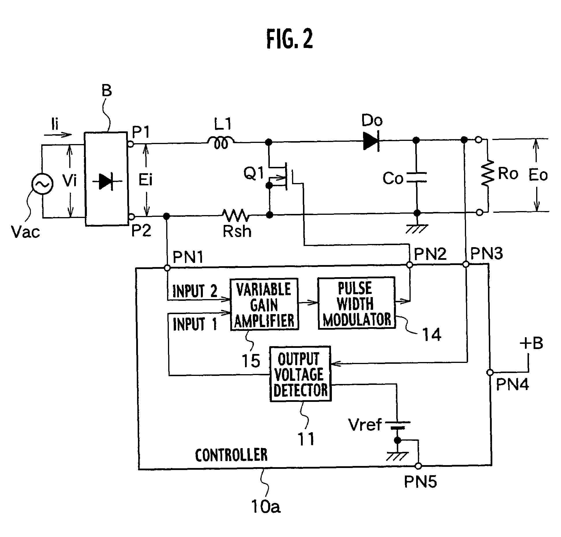
[0038]A power factor improving circuit according to the first embodiment shown in FIG. 2 is different from the conventional power factor improving circuit shown in FIG. 1 only in structure of a controller 10a.

[0039]Other structures shown in FIG. 2 are the same as those shown in FIG. 1. Like parts are designated with like reference numerals and detailed explanation thereof will be omitted.

[0040]The controller 10a includes an output voltage detector 11, a variable gain amplifier 15 and a pulse width modulator 14.

[0041]The output voltage detector 11 amplifies a difference between voltage of a smoothing capacitor Co and a reference voltage Vref, generates error voltage and output the same to the variable gain amplifier 15. The variable gain amplifier 15 varies a gain in accordance with a value of the error voltage from the output voltage detector 11, thereby amplifying the voltage which is proportional to the input current detected by the current detecting resistor Rsh, and outputs the...

second embodiment

[0060]FIG. 8 is a block diagram showing a power factor improving circuit according to a second embodiment. The second embodiment is different from the first embodiment shown in FIG. 2 in the current detector method of the input, and current conducting through the switch Q1 is detected in the second embodiment.

[0061]In the power factor improving circuit shown in FIG. 8, a series circuit comprising a step up reactor L1, a diode Do and a smoothing capacitor Co is connected to both output ends of a full-wave rectification circuit B which rectifies AC current of an AC power supply Vac. A load Ro is connected to both ends of the smoothing capacitor Co.

[0062]A controller 10b includes a switch Q1, a current detecting resistor Rsh, a peak detector 16, an operational amplifier 11 as an output voltage detector, a variable gain amplifier 15, and a pulse width modulator 14.

[0063]One end (drain) of the switch Q1 is connected to a connection between a step up reactor L1 and an anode of a diode Do ...

third embodiment

[0067]FIG. 9 is a block diagram showing a power factor improving circuit according to a third embodiment. The power factor improving circuit is applied to a converter which is so-called a choke converter. The third embodiment is different from the first embodiment in the structure of a rectification smoothing circuit connected to both ends of the switch Q1. The rectification smoothing circuit comprises a first series circuit including a diode Do and a capacitor Cx connected to both ends (between drain and source) of the switch Q1, and a second series circuit including a smoothing capacitor Co and a reactor Lo connected to both ends of the diode Do. A controller 10c is different from the controller 10a shown in FIG. 2 in that a negative pole of a reference voltage Vref is connected to an operational amplifier 11 as an output voltage detector, and a positive pole is grounded.

[0068]The power factor improving circuit according to this embodiment is also operated in the same manner as th...


PUM


Abstract

The power factor improving circuit has a current detecting resistor Rsh for detecting current conducting through a set up reactor L1 or current conducting through a switch Q1, an output voltage detector 11 which amplifies a difference between output voltage Eo and reference voltage Vref to generate error voltage, a variable gain amplifier 15 which amplifies voltage which is proportional to current detected by the current detecting resistor Rsh by varying gain in accordance with a value of the error voltage of the output voltage detector 11, and a pulse width modulator 14 which generates a pulse signal whose pulse width is controlled in accordance with a value of output of the variable gain amplifier 15 and which applies the pulse signal to the switch Q1 to control the output voltage Eo to predetermined voltage.

Description

BACKGROUND OF THE INVENTION[0001]The present invention relates to a simple and inexpensive power factor improving circuit, and more particularly, to a technique of a control circuit of the power factor improving circuit.[0002]FIG. 1 is a block diagram of a conventional power factor improving circuit. In the power factor improving circuit shown in FIG. 1, a series circuit includes a step up reactor L1, a switch Q1 comprising an MOSFET and a current detecting resistor Rsh are connected to both output ends of a full-wave rectification circuit B which rectifies AC current of an AC power supply Vac. A series circuit includes a diode Do and a smoothing capacitor Co is connected to both ends (between a drain and a source) of the switch Q1. A load Ro is connected to both ends of the smoothing capacitor Co. The diode Do and the smoothing capacitor Co constitute a rectification smoothing circuit. The switch Q1 is turned ON / OFF by PWM control of a controller 10.[0003]The current detecting resi...

Claims


Application Information

Patent Timeline
Patent Type & Authority Patents(United States)
IPC IPC(8): G05F1/40H02M7/12H02M1/42H02M3/00H02M3/04H02M3/155H02M3/28H02M7/46
CPCH02M1/4225H02M1/4258H02M2001/0025Y02B70/126Y02B70/10Y02P80/10H02M1/0025H02M1/0085
Inventor MORITA, KOICHI
Owner SANKEN ELECTRIC CO LTD
Why Eureka
Try Eureka