Data partitioning for multi-link transmission

Active Publication Date: 2007-04-10
STMICROELECTRONICS INT NV
View PDF27 Cites 50 Cited by
  • Summary
  • Abstract
  • Description
  • Claims
  • Application Information

AI Technical Summary

Benefits of technology

[0018]It is an object of the present invention to provide

Problems solved by technology

IMA is typically used to serve sites for which a single E1 or T1 line does not give sufficient bandwidth, while a high-rate interface is not needed or economically justified.
This approach has some disadvantages that stem from the fact that the values of N1 and N2 can be up to several hundred.
It can be seen that this block-based splitting scheme does not give good interleaving of bytes between the two subchannels.
Therefore, if one of the subchannels has a lower noise margin than the other (resulting in a higher incidence of bit errors), the result will be bursts of errors coming from this subchannel in the output data stream at the receiver.
A further disadvantage of this implementation is the need for big input buffers to accumulate at least N1 and N2 bytes at both the transmitter and the receiver.
The ad

Method used


Image

  • Data partitioning for multi-link transmission
  • Data partitioning for multi-link transmission
  • Data partitioning for multi-link transmission

Examples


example 1

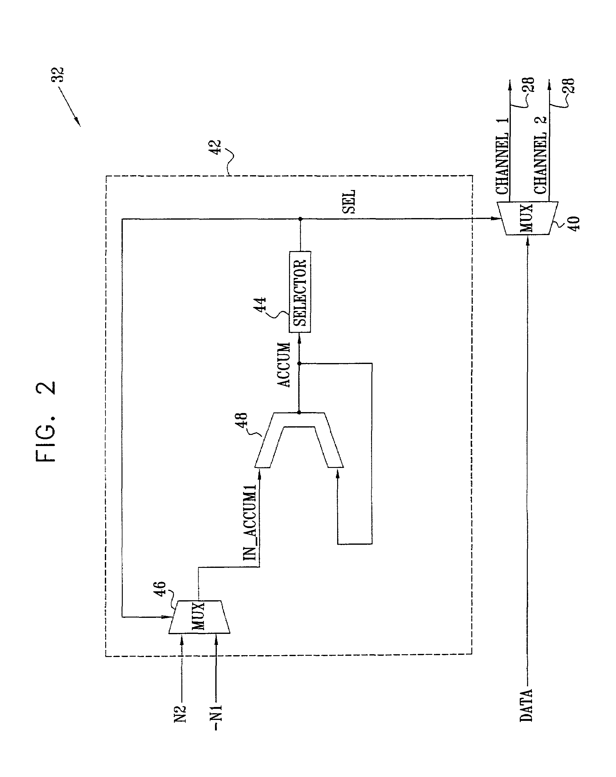
[0079]In this case, the splitting is based on three (M−1)-entry arrays: A[i], C1[i] and C2[i]. A[i] is an accumulator identified with the ith two-way splitter 50, which is updated for each incoming data byte. C1[i] and C2[i] are constants used in incrementing and decrementing the ith accumulator. These constants are pre-calculated during system initialization, and should be updated any time there is a change in at least one subchannel rate. C1[i] and C2[i] are calculated as follows:

[0080]

For i = M / 2 to M−1C1[i] = R[2*i−M+1]C2[i] = R[2*i−M+2]For i = M / 2−1 to 1 (a decreasing index in steps of −1)C1[i] = C1[2*i] + C2[2*i]C2[i] = C1[2*i+1] + C2[2*i+1]

In these calculations, when K

[0081]To begin operation of the multiplexer, all the accumulators A[i] are set to zero. The following calculation is then performed for every incoming data byte:

[0082]

{k = 1For i=1 to L{If (A[k]≧ C1[k]){A[k] = A[k]− C1[k]sel = 1}else{A[k] = A[k] + C2[k]sel = 0}k ...

example 2

[0083]In this method, unlike the preceding one, accumulators A[i] are associated with respective subchannels 28, for i=1, . . . , K, along with a single array of constant parameters C[i]. The parameters C[i] are pre-calculated during system initialization and are updated any time there is a change in at least one of the subchannel rates. In this example, each C[i] is simply set equal to G / R[i], wherein G is the least common multiple (LCM) of R1, R2, . . . RK. Alternatively, other values of G may be used. As before, all the accumulators A[i] are set to zero before beginning operation. The following calculation is then performed for each incoming data byte:

[0084]

{Find j such that A[j] = min(A[i]) over all i ≦ KA[j] = A[j] + C[j]Send data byte to subchannel no. j}

[0085]Splitters 50 are set for each byte so as to select subchannel j, as provided by this calculation. If there is more than one value of j for which A[j]=min(A[i]), the lowest of these values of j may be selected. Alternativ...

example 3

[0088]This method is similar to that described in Example 2, but uses a scaling factor h to keep the accumulator values A[i] within a relatively small range. The parameters C[i] are pre-calculated as in Example 2. Preferably, h is the subchannel index such that C[h]=min(C[i]), taken over all i. Alternatively, h may be chosen to be a different subchannel index. The following calculation is performed for each incoming data byte:

[0089]

{Find j such that A[j] = min(A[i]) over all i ≦ KIf (j≠h)A[j] = A[j] + C[j]ElseA[i] = A[i]− C[j] for all i except jEndSend data byte to subchannel no. j}

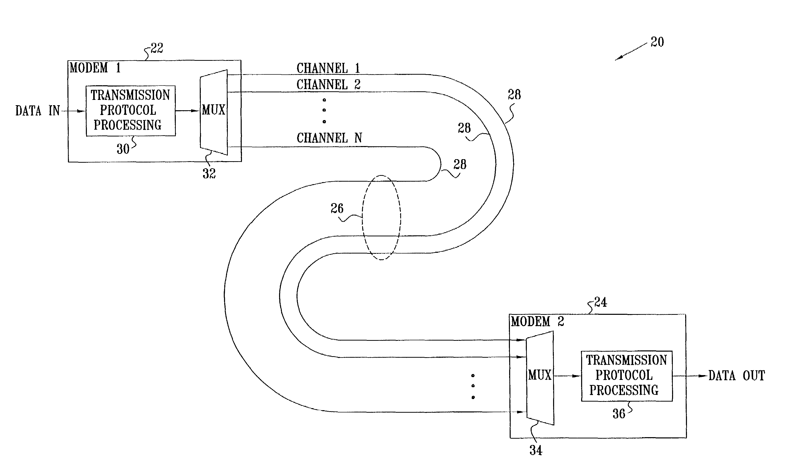
[0090]FIG. 5 is a block diagram that schematically illustrates a multi-pair transmitter 60, in accordance with another preferred embodiment of the present invention. This model is similar to the standard SDSL transmitter reference configuration, as described in Chapter 4 (page 13) of the above-mentioned ETSI standard, except that it is extended to serve K subchannels 28. Typically, in SDSL configurations,...


PUM


Abstract

A method for transmitting a stream of data over a channel made up of a plurality of subchannels having respective subchannel rates. The method includes partitioning the data among the subchannels, such that successive words of the data are mapped to the subchannels in alternation responsive to the respective subchannel rates. The words of the data are transmitted over the subchannels to which they are mapped, and are then received and processed to recover the stream of data.

Description

CROSS-REFERENCE TO RELATED APPLICATIONS[0001]This application claims the benefit of U.S. Provisional Application(s) No(s).: 60 / 266,802, filed Feb. 6, 2001, 60 / 337,038, filed Nov. 7, 2001, 60 / 340,283, filed Dec. 14, 2001, and 60 / 345,492, filed Jan. 3, 2002, and incorporates the same by reference.FIELD OF THE INVENTION[0002]The present invention relates generally to digital communication systems, and specifically to methods and devices for efficiently partitioning a data stream for transmission over multiple subchannels.BACKGROUND OF THE INVENTION[0003]In multi-link transmission, a single data stream is partitioned over a number of parallel links between a transmitter and a receiver. In Asynchronous Transfer Mode (ATM) networks, for example, a multi-link transmission technique known as inverse multiplexing is used. This technique is described in document AF-PHY-0086.001, promulgated by the ATM Forum (1999), entitled “Inverse Multiplexing for ATM (IMA) Specification Version 1.1,” which...

Claims


Application Information

Patent Timeline
IPC IPC(8): H04J3/24H04L12/28H04L12/56H04L25/14H04L27/26
CPCH04L25/14H04L2012/565H04L2012/5672H04Q2213/13039
Inventor AMIDAN, MORANFRENKEL, LIRONYANKO, HAIM
Owner STMICROELECTRONICS INT NV
Why Eureka
Try Eureka