Carburetor electrically-operated automatic choke system

an automatic choke and carburetor technology, applied in the direction of electrical control, heating types, separation processes, etc., can solve problems such as difficulty in starting the engine, and achieve the effect of reliable starting the engin

Active Publication Date: 2007-04-17
HONDA MOTOR CO LTD
View PDF7 Cites 11 Cited by
  • Summary
  • Abstract
  • Description
  • Claims
  • Application Information

AI Technical Summary

Benefits of technology

[0011]With the above-described features of the present invention, while the engine is running, the electric motor, which is controlled by the electronic control unit, drives the choke valve to an appropriate opening degree according to a rise or fall in the temperature of the engine, thus supplying an air-fuel mixture of an appropriate concentration to the engine. Furthermore, when the engine stops running, the choke valve closure spring and the wax-type temperature sensitive actuating device cooperate with each other such that the opening degree of the choke valve is automatically controlled to a start opening degree that corresponds to the engine temperature. Therefore, it is possible to reliably start the engine, regardless of whether the engine is cold or hot, even when the electric motor is in an inoperable state while the engine is being started.

Problems solved by technology

However, in the case where the system has no battery and an electric motor is operated using power generated by a generator driven by an engine, or, in the case where the system has a battery but the amount of electricity stored in the battery is insufficient while being cold-started, even if the electric motor does not operate, the choke valve remains open, and a rich air-fuel mixture suitable for a cold start cannot be generated in an intake path of the carburetor, making it difficult to start the engine.

Method used


Image

  • Carburetor electrically-operated automatic choke system
  • Carburetor electrically-operated automatic choke system
  • Carburetor electrically-operated automatic choke system

Examples


second embodiment

[0035]the present invention is now explained by reference to FIG. 6.

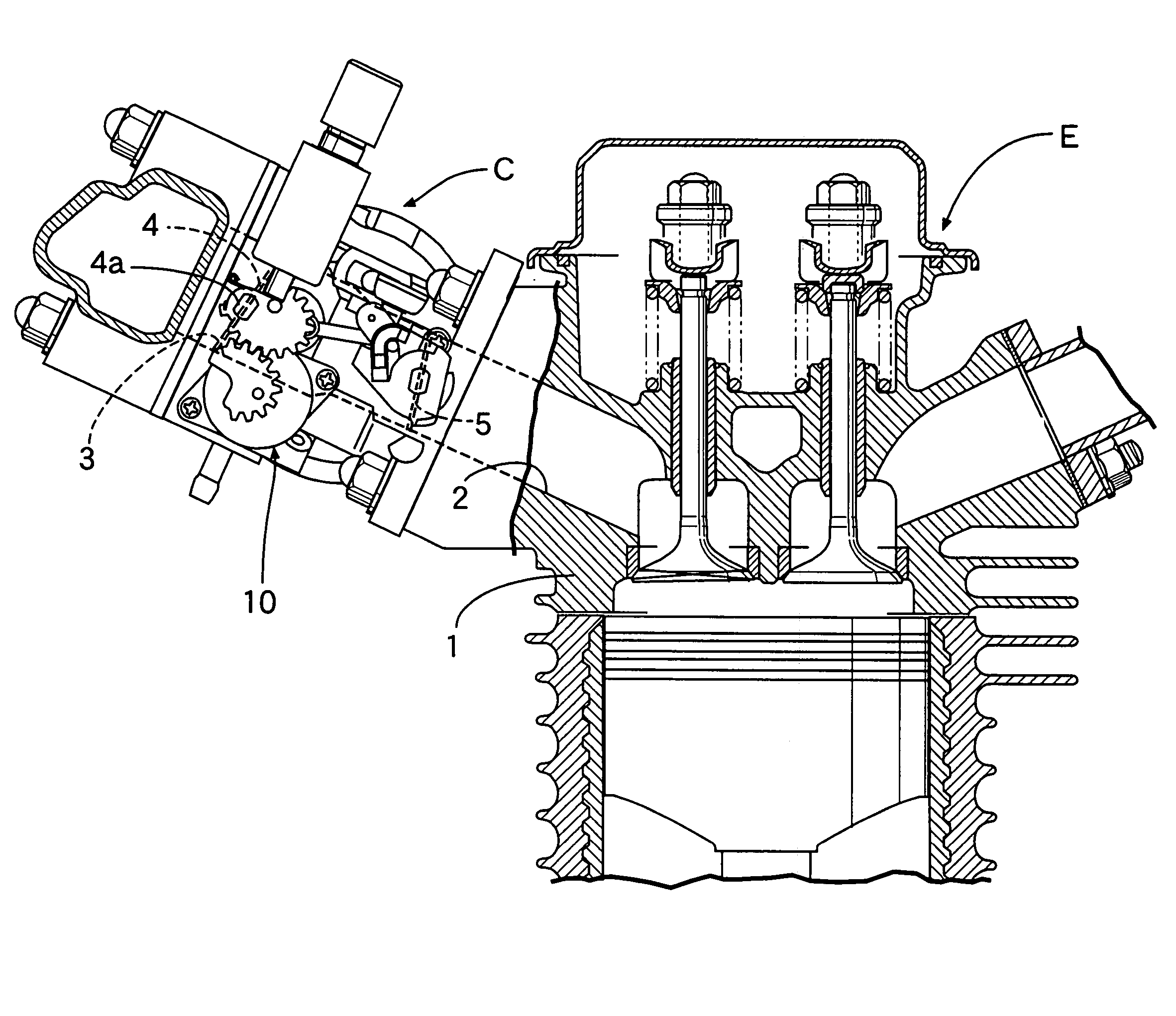
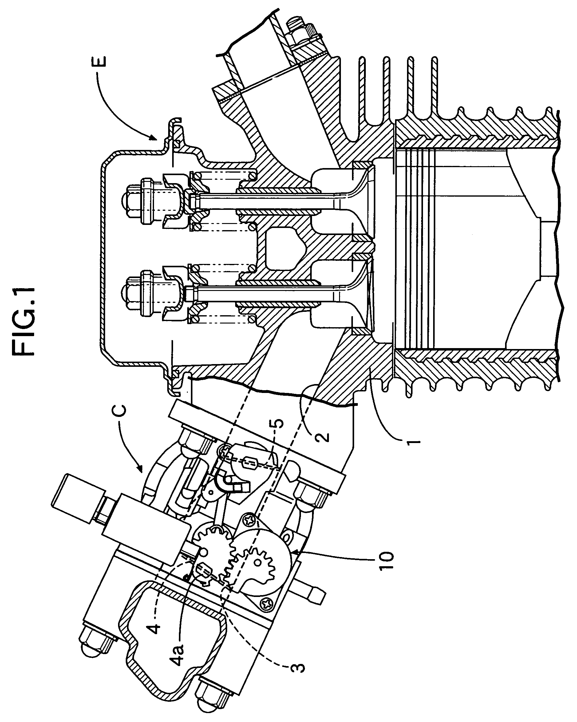
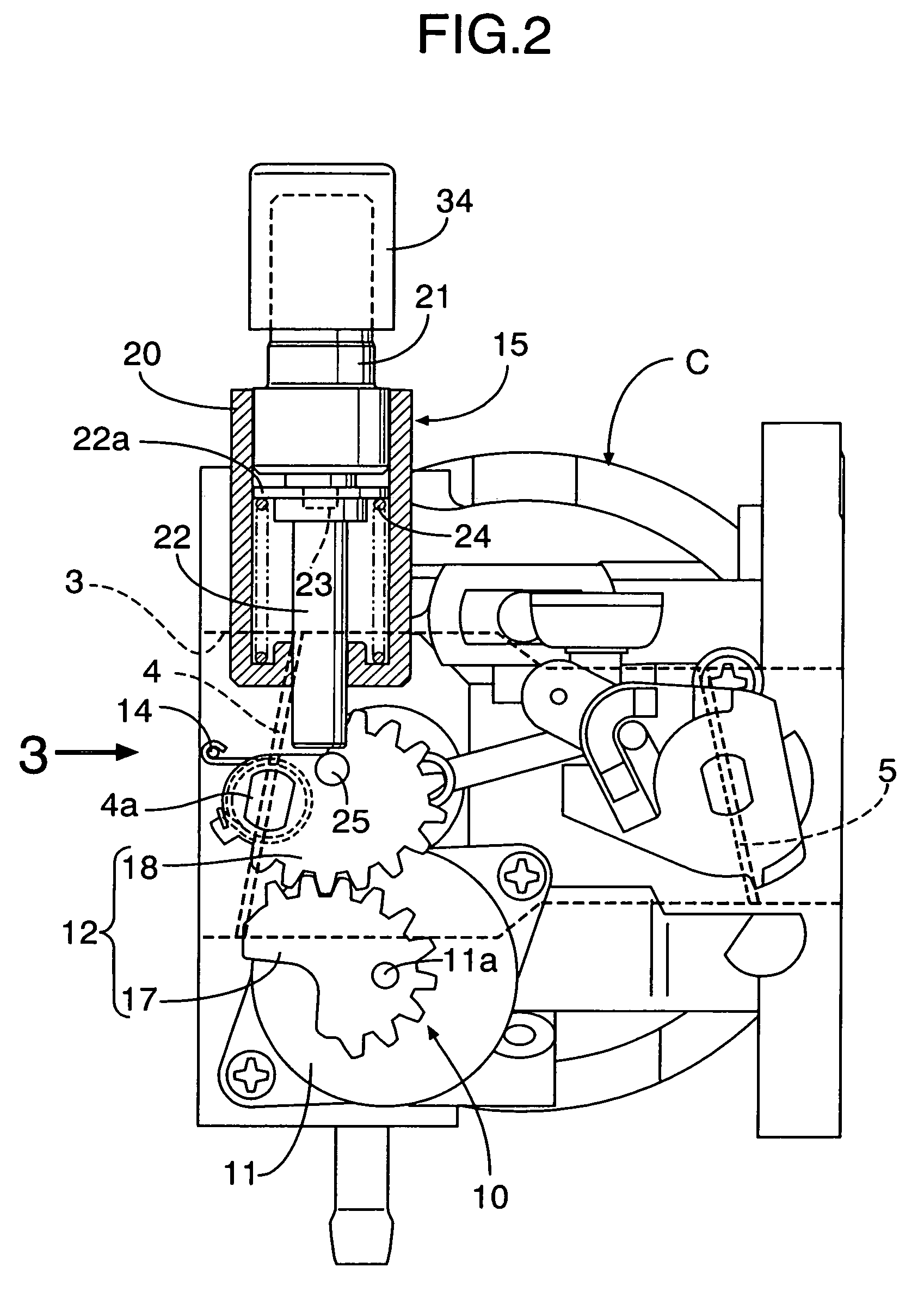
[0036]The second embodiment directly uses the heat of the cylinder head 1 of the engine E to heat the wax case 21 of the wax-type temperature sensitive actuating device 15. Specifically, the wax-type temperature sensitive actuating device 15 is positioned so that the wax case 21 faces the cylinder head 1 side of the engine E. Fitted around the outer periphery of the wax case 21 is a heat transmitting member 36 with a tip end inserted into a depression 35 on an outer face of the cylinder head 1, thus transmitting heat of the cylinder head 1 to the wax case 21 via the heat transmitting member 36.

[0037]A stop lever 34 is secured to the choke valve shaft 4a while being superimposed on the non-constant speed driven gear 18. The piston member 22 of the temperature sensitive actuating device 15 is disposed to face the stop lever 34 so as to make contact with, or move away from, the stop lever 34 on a pivoting path of the s...


PUM

PropertyMeasurementUnit
drive torqueaaaaaaaaaa
temperatureaaaaaaaaaa
rotational radiusaaaaaaaaaa

Abstract

An electrically-operated automatic choke system of a carburetor includes a choke valve connected to a choke valve closure spring that urges the choke valve in a direction to close it. A wax-type temperature sensitive actuating device is coupled to the carburetor to receive heat generated by an engine. A piston member of the device faces a pivoting member coupled to the choke valve and makes contact with, or moves away from, the pivoting member on a pivoting path to the closed side of the choke valve. While the engine has stopped running, closure of the choke valve by the choke valve closure spring is restricted according to the amount the piston member protrudes.

Description

RELATED APPLICATION DATA[0001]The Japanese priority application No. 2004-246531 upon which the present application is based is hereby incorporated in its entirety herein by reference.BACKGROUND OF THE INVENTION[0002]1. Field of the Invention[0003]The present invention relates to a carburetor having an electrically-operated automatic choke system that is primarily applied to a general purpose engine, and particularly, to an electrically-operated automatic choke-system that includes an electric motor, a transmission device for transmitting a driving torque of the electric motor to a choke valve of the carburetor in directions to open and close the choke valve, and an electronic control unit for controlling operation of the electric motor.[0004]2. Description of the Related Art[0005]Such an electrically-operated automatic choke system of a carburetor is known from, for example, Japanese Patent Application Laid-open No. 58-155255.[0006]Since a conventional electrically-operated automati...

Claims


Application Information

Patent Timeline
Patent Type & Authority Patents(United States)
IPC IPC(8): F02M1/00B01D47/00F02M1/08F02M1/10F02N99/00
CPCF02D41/067F02M1/12F02D41/042F02N19/001
Inventor MATSUDA, HAYATO
Owner HONDA MOTOR CO LTD
Why Eureka
Try Eureka