Temperature compensated, high efficiency, controlled input impedance diode detector

a diode detector and input impedance technology, applied in the direction of amplitude demodulation, pulse automatic control, electrical apparatus, etc., can solve the problems of complex circuit design, poor thermal stability of the circuit, and high cost, size, weight, and power requirements of the differential amplifier,

US7205832B2Inactive Publication Date: 2007-04-17VECTRON INT INC
10 Cites 4 Cited by

Patent Information

Authority / Receiving Office
US · United States
Patent Type
Patents(United States)
Current Assignee / Owner
Publication Date
2007-04-17
Estimated Expiration
Not applicable · inactive patent

Smart Images

  • Figure 1
    Figure 1
  • Figure 2
    Figure 2
  • Figure 3
    Figure 3
Patent Text Reader

Abstract

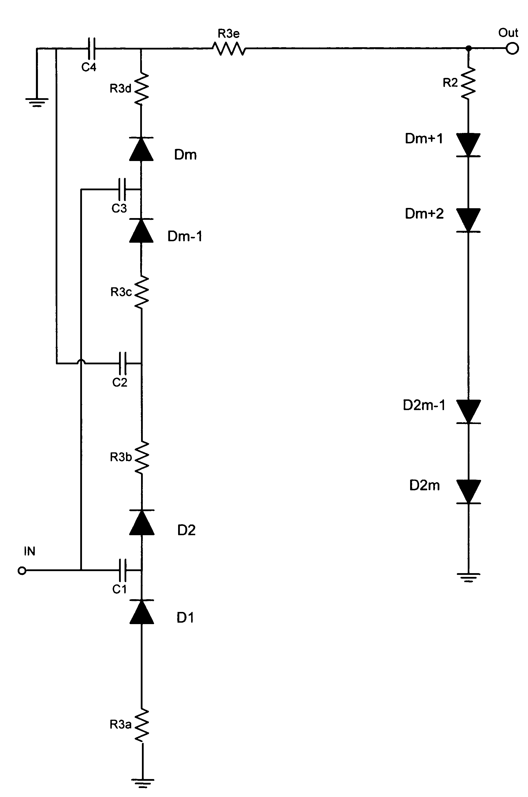
A diode detector comprising a detector network adapted to detect and multiply the detected voltage coupled to a divider network that comprise diodes in equal number to the number of diodes in the detector network, provides a passive detector applicable to any application requiring a small, efficient, high output, inexpensive temperature compensated detector for use as demodulator or as power to voltage converter. Integrating a portion of the divider network in the detector / multiplier network allows control over the minimum input impedance of the detector.
Need to check novelty before this filing date? Find Prior Art

Description

RELATED APPLICATIONS

[0001] This application is a continuation in parts of U.S. patent application Ser. No. 10 / 429,151 filed May 2nd 2003 presently U.S. Pat. No. 6,825,715, the application is hereby incorporated by reference in its entirety.FIELD OF THE INVENTION

[0002] This invention relates to diode detector circuits and more particularly to a passive, temperature compensated high efficiency diode detectorBACKGROUND OF THE INVENTION

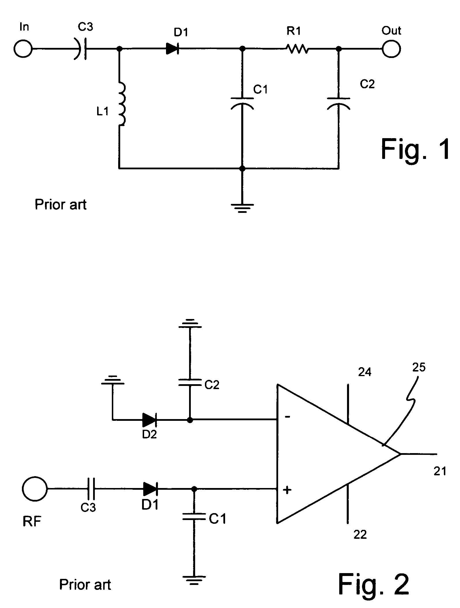
[0003] Diode detectors had been known in the art from the first days of radio. They are used to demodulate radio frequency (RF) or any other alternating current (AC) signal and turn it into voltage representative of the modulating waveform. A common diode detector is shown in FIG. 1. AC, sonic, sub sonic, ultra sonic or RF energy and the like (commonly referred to as RF hereinafter) is rectified by diode D1 that acts as a non-linear element for the conversion. While a Schottky diode is preferred, alternative asymmetric junctions are also suitable. The rectif...

Examples

Embodiment Construction

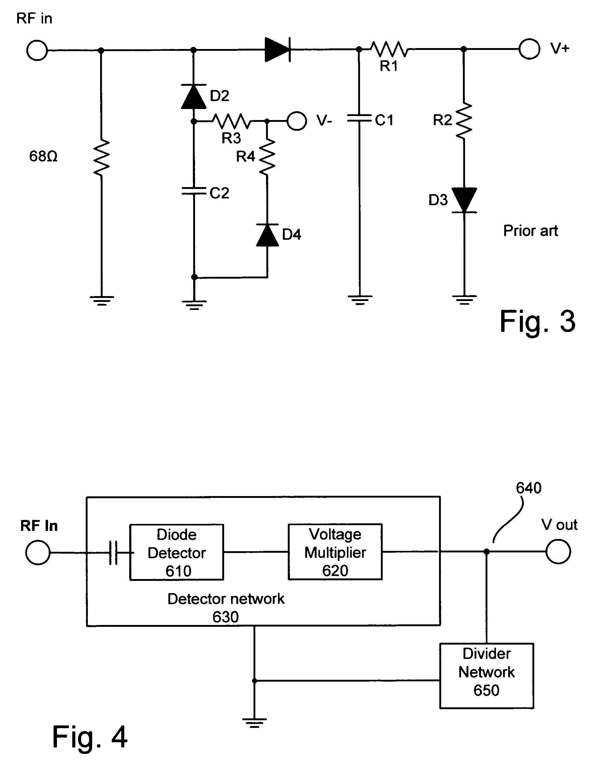
[0029]Referring now to FIG. 4 a most basic embodiment of the invention disclosed in Ser. No. 10 / 429,151 is shown. An RF (or any frequency) signal is inputted via input terminal RFin, into detector network 630. Detector network 630 comprises at least two basic components—a diode detector 610 and a voltage multiplier 620. Those skilled in the art will recognize that the diode used in the diode detector 610 may be utilized as a part of the voltage multiplier 620, or the detector may be separate from the voltage multiplier. In the preferred embodiment the voltage multiplier is a voltage doubler, comprising of the detector diode and a multiplier diode, however any number of diodes may be used, to provide voltage multiplication of any factor.

[0030]Divider network 650 is coupled to the output of the detector network at junction 640, and as it is coupled to the circuit ground (equivalently referred to as ground in these specifications), it forms a voltage divider together with the detector ...