U/Z-shaped steel bar manufacturing process

a manufacturing process and steel bar technology, applied in the field of steel bar manufacturing process, can solve the problems of high investment cost, poor quality of finished product, and large installation space for multiple hydraulic punch presses and punch dies, and achieve the effects of preventing deformation of finished product, simple and efficient manufacturing process, and maintaining the quality of finished produ

Inactive Publication Date: 2007-04-24
CHUANG SEN JUNG
View PDF8 Cites 18 Cited by
  • Summary
  • Abstract
  • Description
  • Claims
  • Application Information

AI Technical Summary

Benefits of technology

[0005]The present invention has been accomplished under the circumstances in view. It is therefore the main object of the present invention to provide an U/Z-shaped steel bar manufacturing process, which eliminates the aforesaid drawbacks. According to one aspect of the present invention, the steps of: (a) material supply, (b) material flattening, (c) material punch-hole punching and length-cutting, (d) material shape forming through a roll forming machine, (d) finished product straightening, and (e) finished product packing. This manufacturing process is simple and efficient, preventing deforma

Problems solved by technology

1. When punched by the punch die 931 of the hydraulic punch press 93 or cut by the hydraulic cutting die 932, the continuous sheet of U-shaped steel bar 901 or Z-shaped steel bar 902 tends to be deformed, resulting in poor quality of finished product.
2. One punch press can only punch the continuous sheet of U-shaped steel bar 901 or Z-shaped steel bar 902 with a predetermined pattern of punch holes 9011 or 9021. For punching punch holes 9011, 9

Method used


Image

  • U/Z-shaped steel bar manufacturing process
  • U/Z-shaped steel bar manufacturing process
  • U/Z-shaped steel bar manufacturing process

Examples


Embodiment Construction

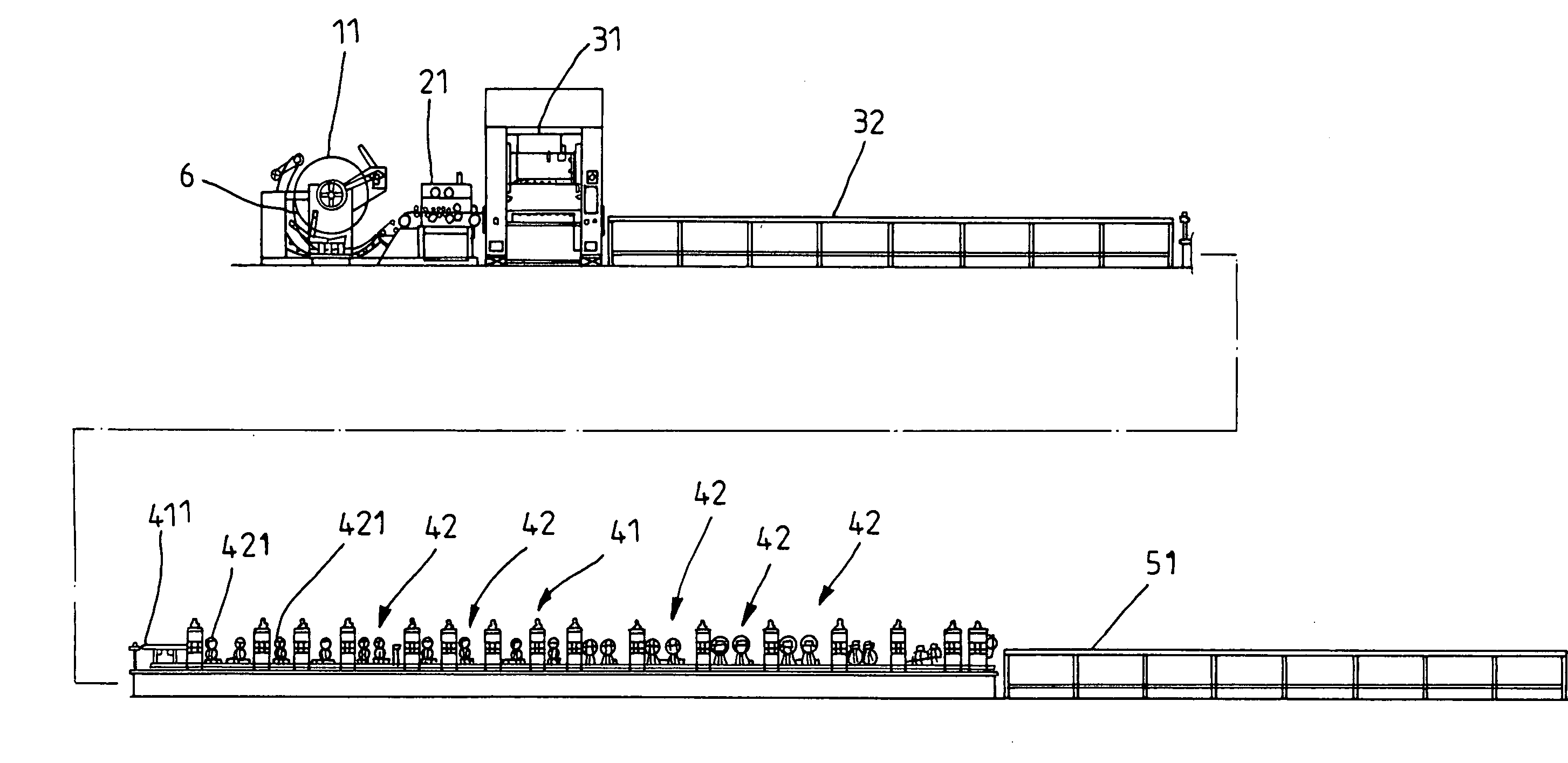
[0032]Referring to FIGS. 17˜20, an U / Z-shaped steel bar manufacturing process in accordance with the present invention includes the steps of:

[0033](1) Material supply, where a roll of steel sheet material 6 is supplied from the spindle of a material rack 11 to a flattening machine 21;

[0034](2) Flattening, where the supplied steel sheet material 6 is flattened by the flattening machine 21 and delivered forwards to a punch press 31 for punching;

[0035](3) Punching and cutting, where the flattened steel sheet material 6 is selectively punched with punch holes 611, 612, 613, 614 or 6011, 6012, 6013, 6014 by the movable punch dies 311, 312, 313, 314, 315 subject to a predetermined punch pattern (see FIGS. 19, 20, and 21) and then cut off subject to the desired length;

[0036](4) Roll forming, where the punched steel sheet material 6 is conveyed by a conveyer 32 to the entrance guide 411 of a roll forming machine 41 and then rammed into an U-shaped steel bar 601 (see FIG. 21) or Z-shaped ste...


PUM


Abstract

Disclosed is an U/Z-shaped steel bar manufacturing process, which includes the steps of (a) supplying a steel sheet material from a material rack to a flattening machine, (b) operating the flattening machine to flatten the steel sheet material and then delivering the steel sheet material to a punch press for punching, (c) operating the punch press to selectively drive the punch dies to punch the steel sheet material with punch holes subject to a predetermined punch pattern, (d) delivering the punched steel sheet material to a roll forming machine and then operating the roll forming machine to ram the punched steel sheet material into an U/Z-shaped steel bar, (e) operating a straightening machine to straighten the U/Z-shaped steel bar, and (f) operating a conveyer to carry the finished product backwards for packing and further delivery or storage.

Description

BACKGROUND AND SUMMARY OF THE INVENTION[0001]The present invention relates to steel bar manufacturing process and more particularly, to an U / Z-shaped steel bar manufacturing process, which is practical to make U / Z-shaped steel bars having punch holes of different punch patterns.[0002]FIG. 1 illustrates an U / Z-shaped steel bar manufacturing flow according to the prior art. The method comprises the steps of (1) material supply where a steel sheet material 90 is let off from the spindle of a material rack 91 to a roll forming mechanism 92, (2) roll forming where the steel sheet material 90 is rolled into a continuous sheet of U-shaped steel bar 901 or Z-shaped steel bar 902 by the roll forming mechanism 92 (see FIGS. 2 and 3), (3) punching and cutting where the punch die 931 of a hydraulic punch press 93 is operated to punch the continuous sheet of U-shaped steel bar 901 or Z-shaped steel bar 902 with punch holes 9011 or 9021 (see FIGS. 4 and 5) and then a hydraulic cutting die 932 is ...

Claims


Application Information

Patent Timeline
IPC IPC(8): B21D28/26B21D5/08
CPCB21D28/26B21D35/00Y10T83/8727Y10T83/943
Inventor CHUANG, SEN-JUNG
Owner CHUANG SEN JUNG
Why Eureka
Try Eureka