Feedback control method for a heliostat

a solar collector and heliostat technology, applied in the field of heliostat solar collectors, can solve the problems of affecting affecting the so as to improve the pointing accuracy of the heliostat, accurate solar energy is reflected onto the receiver

Inactive Publication Date: 2007-04-24
SOLARRESERVE TECH +1
View PDF8 Cites 74 Cited by
  • Summary
  • Abstract
  • Description
  • Claims
  • Application Information

AI Technical Summary

Benefits of technology

[0008]Generally, the present invention utilizes feed-forward predictive software to determine the general position of a solar plant heliostat. More particularly, the present invention provides apparatus and methods for closed loop control of the position of a movable heliostat used in a solar power receiver system. Briefly, the provided systems and methods utilize optics to provide feedback control to the heliostats so that they more accurately reflect solar energy onto a receiver. According to the principles of the present invention, a viewfinder acquires an image of the receiver and an image of the sun reflected off the movable heliostat. By super-imposing the two images, the viewfinder detects whether an offset exists between the two images. If an offset is detected the viewfinder determines the magnitude and direction of the offset. The viewfinder then generates a position error signal used to re-position the heliostat, thereby improving the pointing accuracy of the heliostat.
[0011]Thus, the present invention essentially continuously compensates for positional errors of the heliostat and accurately compensates for such errors so that for the heliostats efficiently direct the solar energy on to the receiver.

Problems solved by technology

However, this aiming strategy is often inaccurate.
Inaccuracies in the positioning of the heliostats results in efficiency losses of the central receiver solar plant.
More specifically, if a heliostat fails to reflect the sun light directly on the receiver, a portion of the energy associated with the light will be lost.
Spillage reduces the efficiency of the system and often requires additional heliostats to compensate for the loss, which in turn adds significant plant costs.
Additionally, the aiming inaccuracies can result in thermal damage to structures and devices near the receiver, which will also significantly increase plant costs.
Furthermore, errors in the devices that physically adjust the position of each heliostat, for example, gear backlash and encoder errors can contribute significantly to heliostat positioning inaccuracies.
Therefore, increasing the accuracy and efficiency of a solar plant by increasing the number of heliostats or employing more expensive aiming device significantly increases plant costs.

Method used


Image

  • Feedback control method for a heliostat
  • Feedback control method for a heliostat
  • Feedback control method for a heliostat

Examples


Embodiment Construction

[0020]The following description of the preferred embodiment(s) is merely exemplary in nature and is in no way intended to limit the invention, its application, or uses.

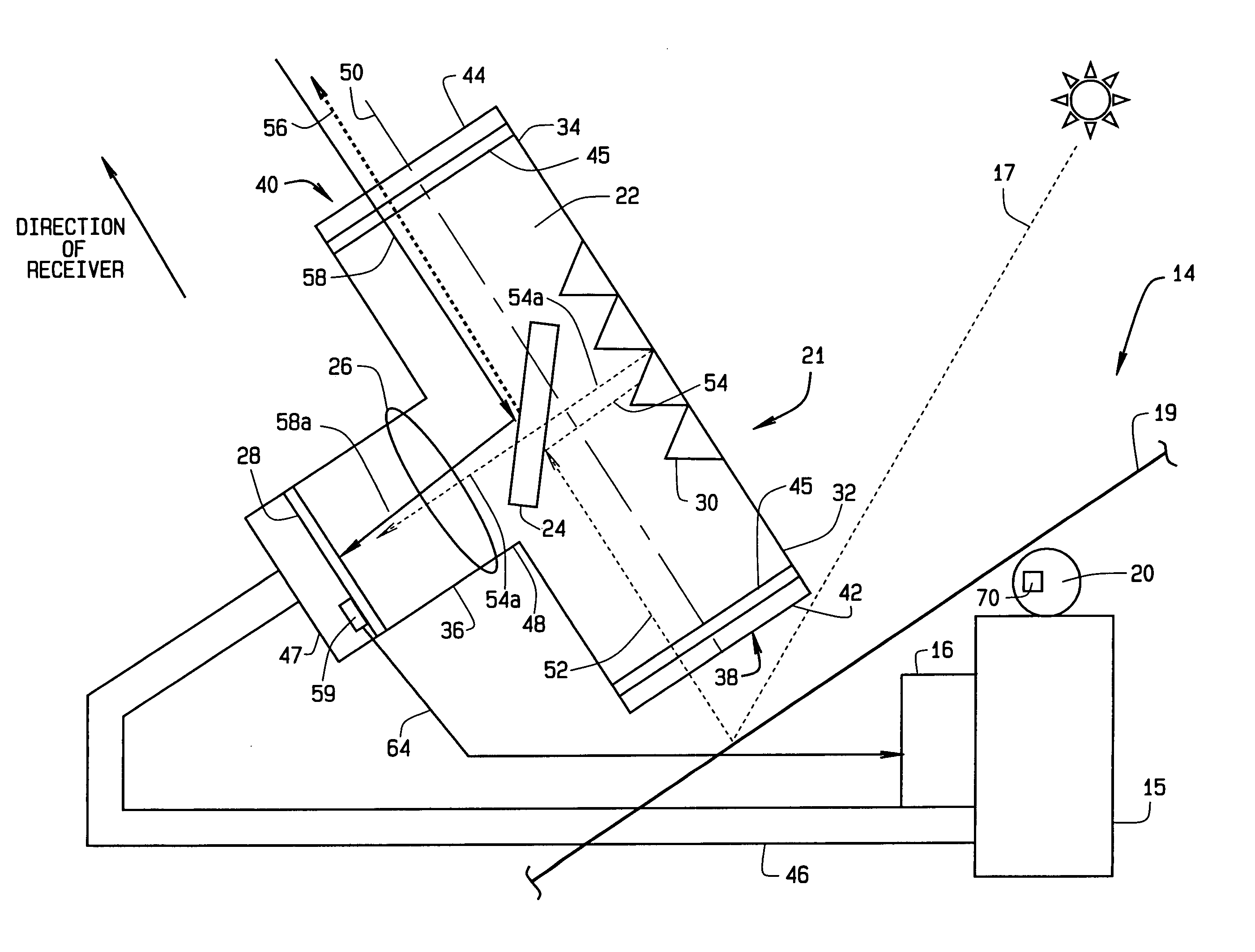
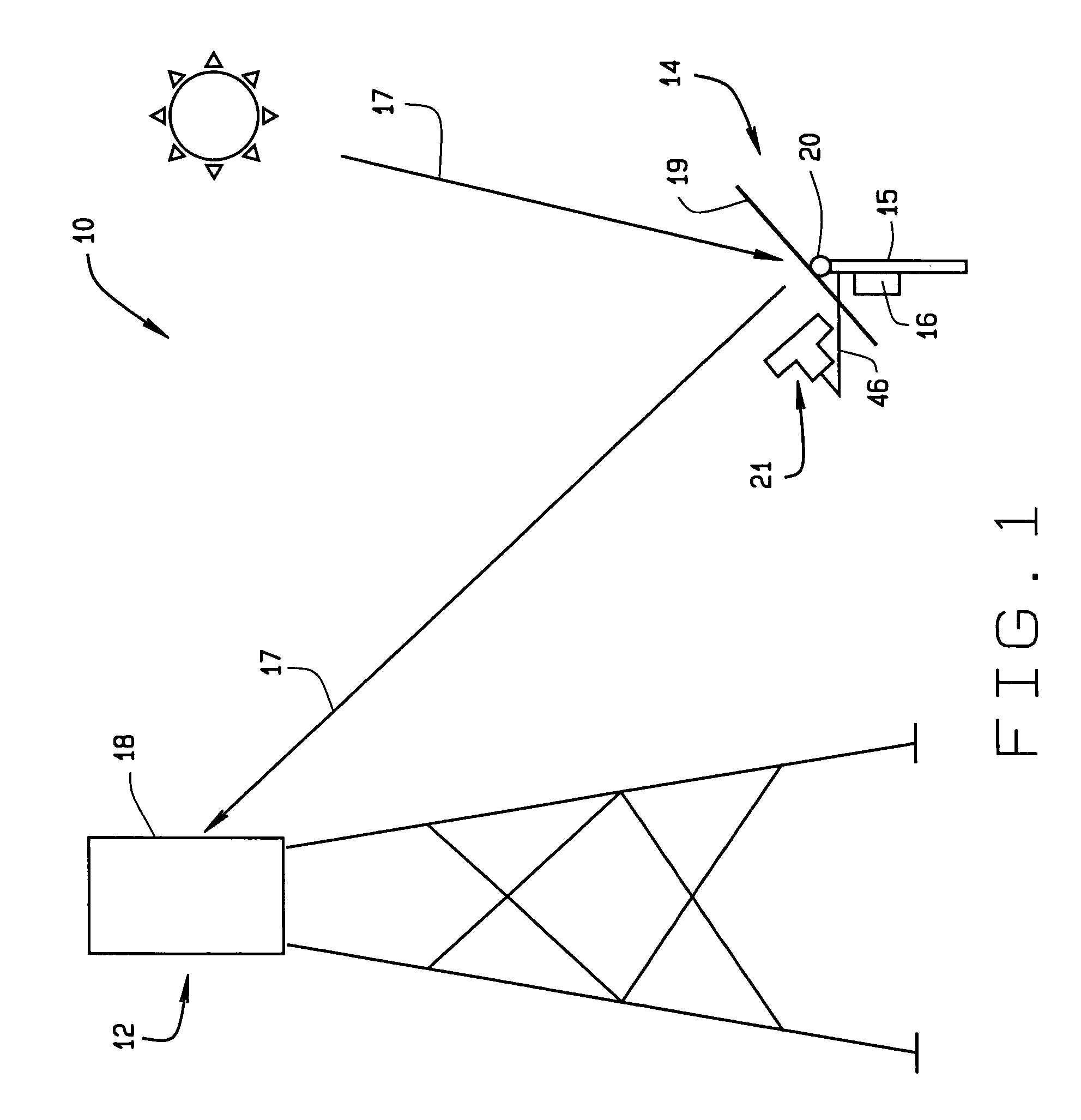
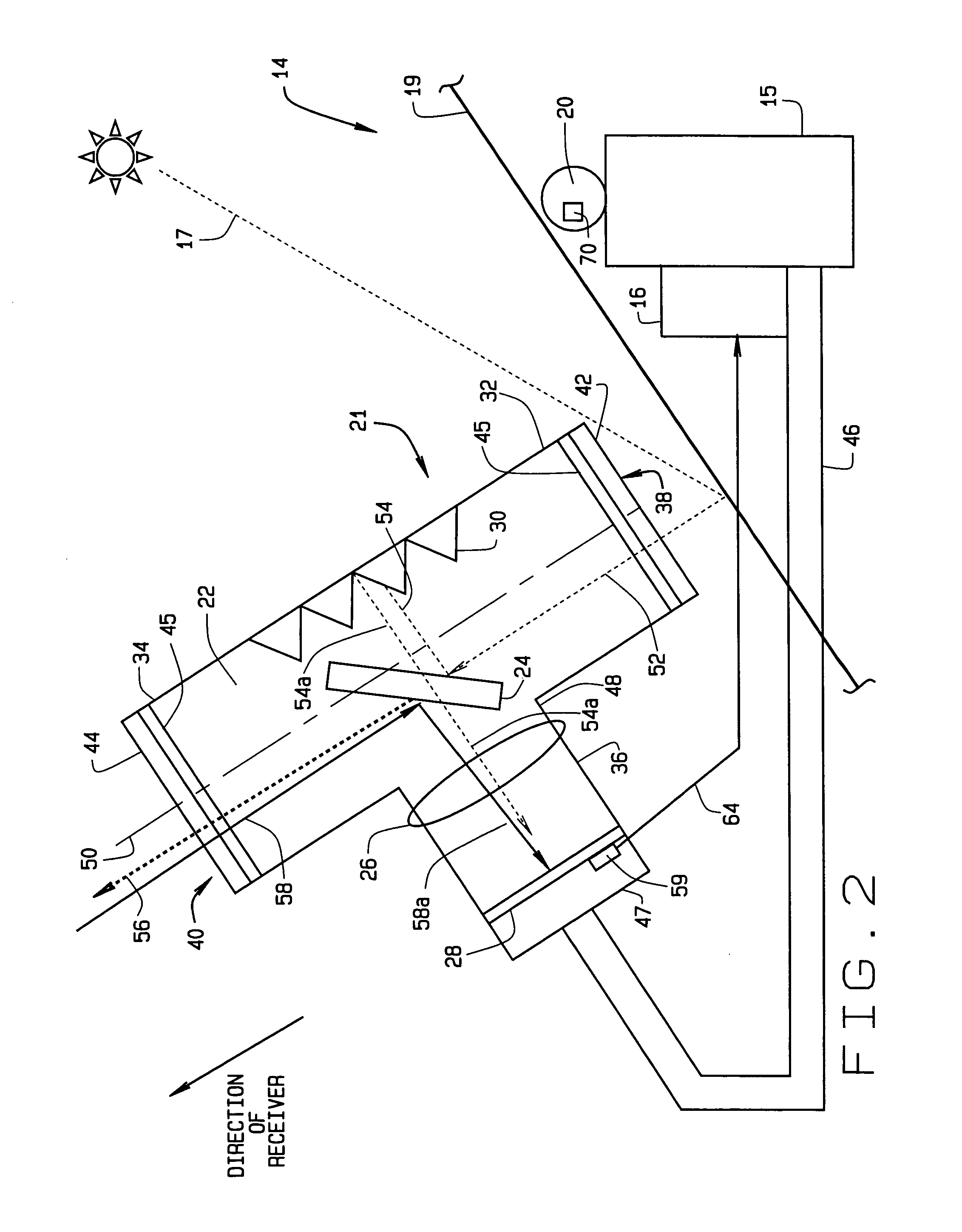
[0021]FIG. 1 illustrates an exemplary solar energy system 10 in accordance with a preferred embodiment of the present invention. The system 10 includes a receiver 12 and at least one heliostat 14. Both the receiver 12 and the heliostat 14 are fixed in location by their respective support structures. Specifically, the heliostat may be supported by a pedestal 15.

[0022]In operation, a controller 16 positions the heliostat 14 using a feed forward, sun-tracking equation, also referred to herein as a prediction equation. Light energy 17 from the sun reflects off the heliostat 14 and is directed toward a surface 18 of the receiver 12. The light energy 17 can be any frequency of light, for example, the light energy 17 can be visible light, infrared light or near infrared light. The heliostat 14 includes a reflective surface 1...


PUM


Abstract

An instrument for a solar energy system including a receiver and a heliostat to reflect solar energy on to the receiver. The instrument includes a first element adapted to form an image of the sun, a second element adapted to form an image of the receiver, and a detector. The detector is positioned to receive each of the images and a comparator is adapted to detect a distance between the images. The comparator generates an error correction signal based on the distance between the images. The error correction signal is received by a controller that controls the operation of a postioner that adjusts the position of the heliostat accordingly.

Description

FIELD OF THE INVENTION[0001]The present invention relates to heliostat solar collectors, and more particularly to heliostat solar collectors that employ closed loop positioning systems.BACKGROUND OF THE INVENTION[0002]To reduce reliance on petroleum and coal based fuels, at least some utilities have turned to solar energy to replace, or augment, conventional electric power plants. In desert regions, where clear days predominate, the switch to solar energy is very desirable. Of several types of solar energy systems, the central solar receiver plant has proven to be a highly reliable and efficient producer of large commercial quantities of power. For example, central solar plants can produce 100 Mwe of power or more.[0003]A solar central receiver plant uses a plurality of sun tracking mirrors called heliostats. The heliostats reflect and concentrate solar energy on to a central receiver. One such system is disclosed in co-pending U.S. application Ser. No. 09 / 879,363, Titled “Thermally...

Claims


Application Information

Patent Timeline
Patent Type & Authority Patents(United States)
IPC IPC(8): F24J2/40F24J2/38G01C21/02G02B5/10G03B21/00F24S23/70F24S23/79F24S50/20
CPCF24J2/10F24J2/38F24J2/40Y02E10/47F24S23/00F24S23/70F24S50/00F24S50/20Y02E10/44
Inventor LITWIN, ROBERT ZMEISTER, CHRISTOPHER D
Owner SOLARRESERVE TECH
Why Eureka
Try Eureka