Lightweight reinforced tractor-trailer slider

a technology for tractor trailers and sliders, applied in convertible cycles, transportation and packaging, cycles, etc., can solve the problems of trailer frame damage, pin locking system not fully engaging the trailer frame, etc., and achieve the effect of improving the structural rigidity of the slider, facilitating the manufacturing of the slider, and increasing the structural rigidity

Active Publication Date: 2007-04-24
ARVINMERITOR TECH
View PDF6 Cites 13 Cited by
  • Summary
  • Abstract
  • Description
  • Claims
  • Application Information

AI Technical Summary

Benefits of technology

[0006]The inventive slider also includes lateral cross-members extending between side rails. The lateral cross-members have an inverted U-shape in one example. The lateral cross-members have tabs on opposing ends that are received in an interlocking relationship with complementary elongated slots in the longitudinal side rails. This interlocking relationship not only improves the structural rigidity of the slider, but also simplifies manufacturing of the slider by improved locating of the lateral cross-members relative to the longitudinal side rails during assembly and welding.
[0007]Air spring supports are arranged at forward and rearward portions of the slider and secured to the longitudinal side rails, the control arm supports, and the lateral cross-members to provide a structurally rigid frame. The air spring supports are generally L-shaped unitary plates that extend from a lower portion of the control arm supports to the lateral cross-members, and generally enclose an opening of the lateral cross-members formed by the inverted U-shape. A portion of a pin locking system, such as the pin linkages, is arranged within a space between the lateral cross-members and the air spring supports to provide protection and support for the pin locking system. The air spring supports provide spaced apart air spring mounting pads that support air springs arranged between the axles and the slider frame. Additional brackets and reinforcements are secured to the slider to provide additional structural rigidity.
[0008]Accordingly, the invention provides a lightweight slider having improved structural rigidity with an increased resistance to racking.

Problems solved by technology

Occasionally, the pins of the pin locking system do not fully engage the trailer frame.
If no pins are engaged, and the trailer stops during operation, the slider may collide with the trailer causing damage to the trailer and / or slider.

Method used


Image

  • Lightweight reinforced tractor-trailer slider
  • Lightweight reinforced tractor-trailer slider
  • Lightweight reinforced tractor-trailer slider

Examples


Embodiment Construction

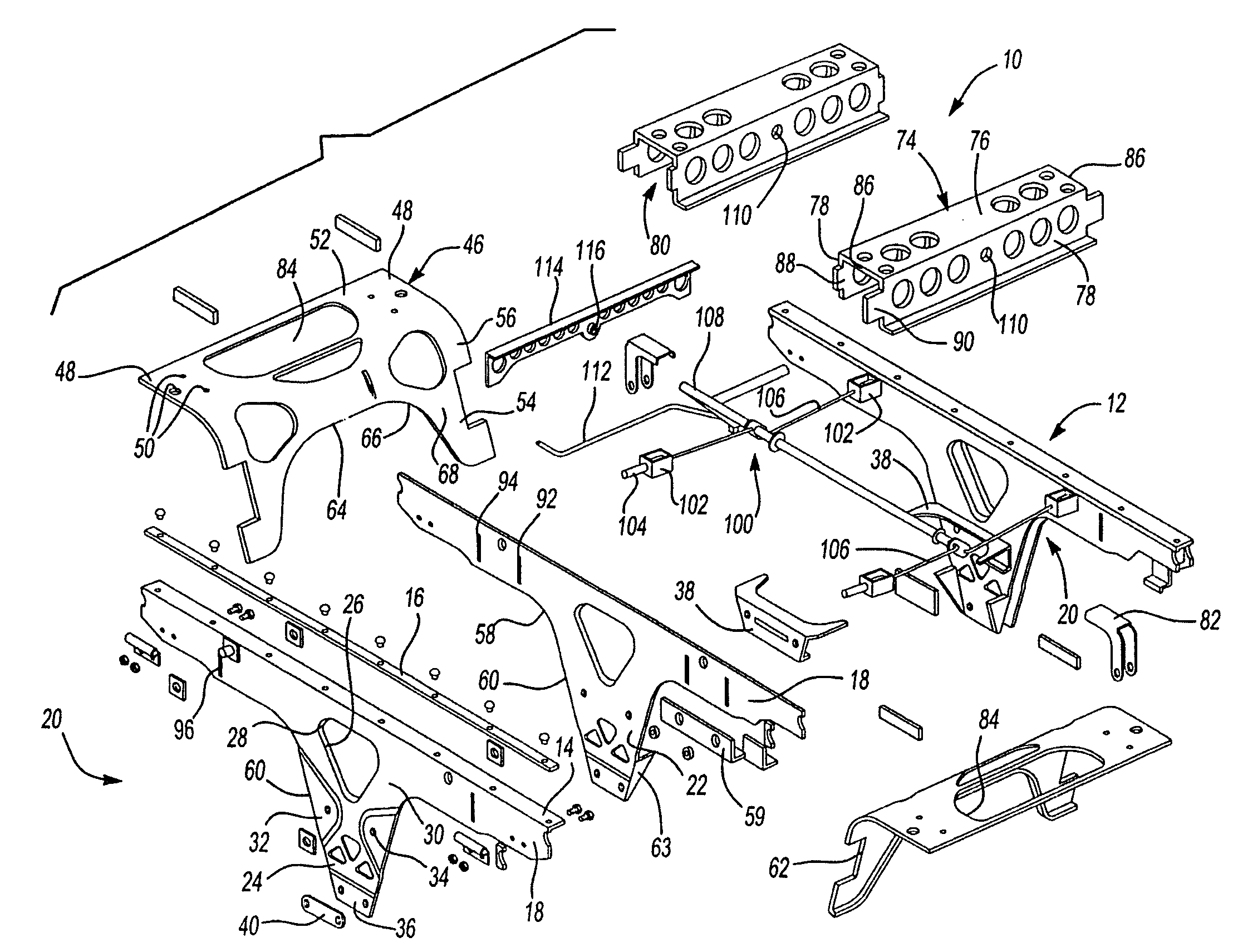
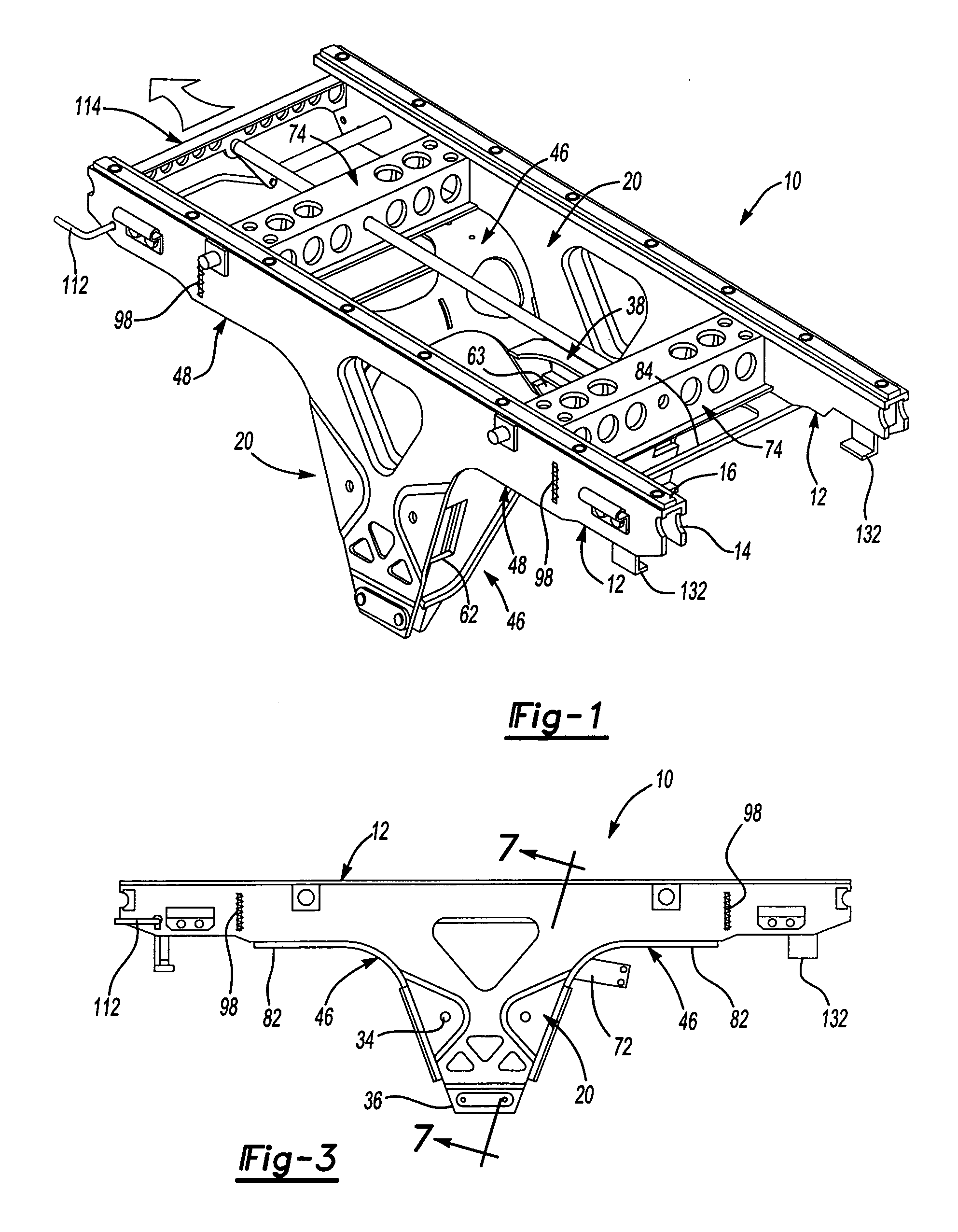
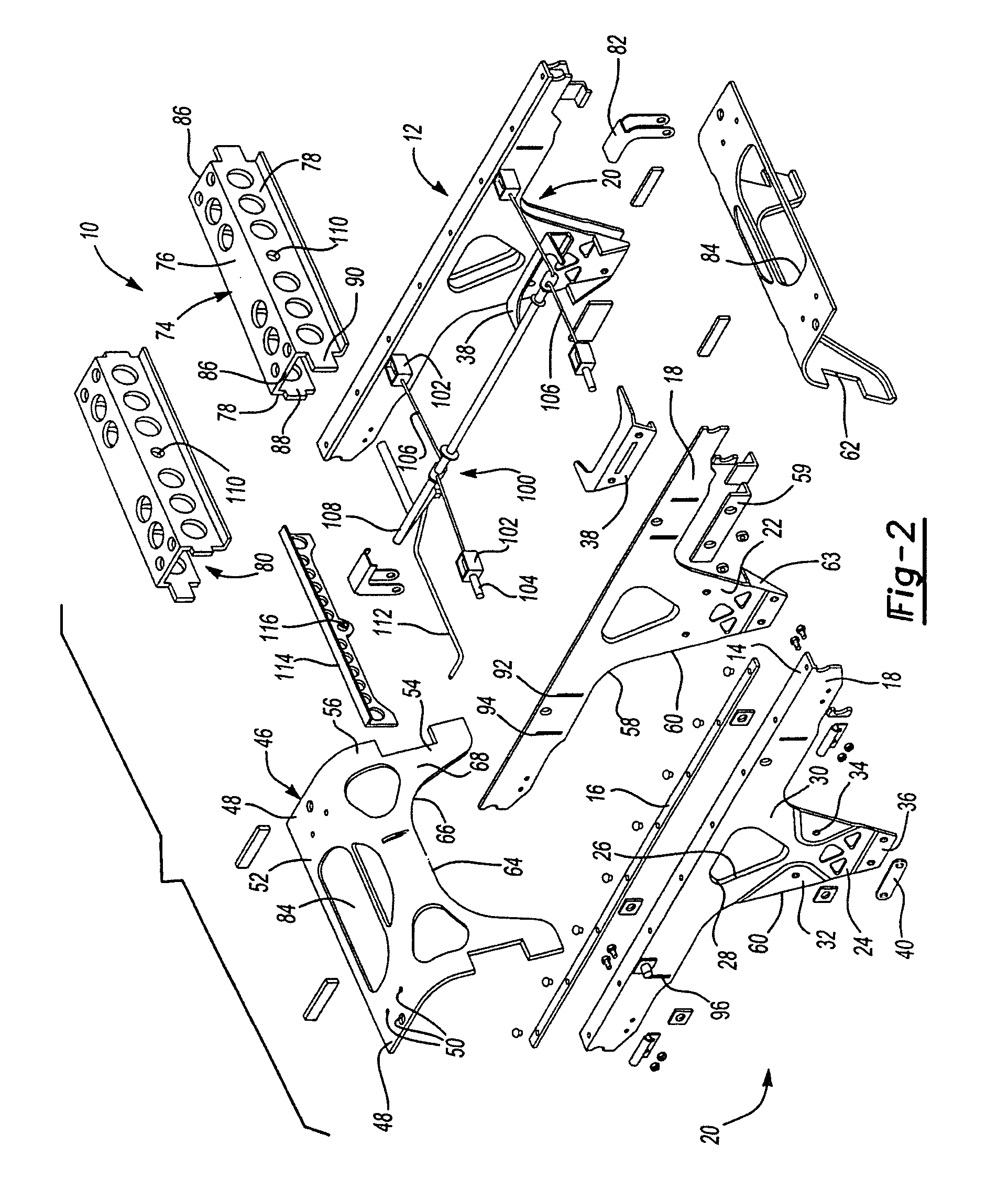
[0018]A slider 10 according to the present invention is shown in FIGS. 1–8. FIGS. 1–7 illustrate the slider 10 with the suspension components removed for clarity. The slider 10 frame structure is preferably constructed from plate steel having mechanical properties specified by ASTM A715 with preferably a minimum yield strength of 76 KSI. However, one of ordinary skill in the art would understand that other types of steels may be used and that the steel thickness may vary throughout the frame structure depending upon the loads exerted, the locations of loads, and the overall stiffness desired for the slider 10. Furthermore, the plates of steel are preferably secured together by welding at intersections between the plates on at least one side of the intersection. Most of the weld beads are not shown for clarity.

[0019]Referring to FIGS. 1–5, the slider 10 includes spaced apart longitudinal side rails 12. The internal structure can be understood from exploded view FIG. 2. The longitudin...


PUM


Abstract

A tractor-trailer slider includes spaced apart longitudinal side rails having control arm supports extending downwardly from the side rails for supporting the slider. Portions of the longitudinal side rails and the control arms supports are integrated using one or more common plates. Lightening holes and edge of the slider are flanged to reinforce the walls. Coining and ribbing are also used for additional reinforcement. Lateral cross-members extend between the longitudinal side rails. The lateral cross-members have tabs on opposing ends that are received in an interlocking relationship with complementary elongated slots in the longitudinal side rails. Air spring supports arranged at forward and rearward portions of the slider are secured to the longitudinal side rails, the control arm supports, and the lateral cross-members to provide a structurally rigid frame. The air spring supports provide spaced apart air spring mounting pads.

Description

BACKGROUND OF THE INVENTION[0001]This invention relates to a tractor-trailer slider, and more particularly, the invention relates to a lightweight frame structure that increases the strength of the slider while reducing its weight.[0002]Sliders are used in the trailer industry for repositioning a trailer suspension relative to a trailer frame to redistribute the load on the axles. To adjust the slider relative to the trailer, a pin locking system is actuated to move pins to an unlocked position. In a locked position, the pins selectively couple the slider to the trailer frame at a desired slider position. With the pins in the unlocked position, the trailer and the tractor are driven to reposition the trailer forward or rearward relative to the slider. The pins are subsequently moved to the locked position once the slider is positioned in the desired slider position.[0003]Occasionally, the pins of the pin locking system do not fully engage the trailer frame. As a result, the slider m...

Claims


Application Information

Patent Timeline
Patent Type & Authority Patents(United States)
IPC IPC(8): B60G5/00B62D53/06B62K13/00
CPCB62D53/068B62D21/02B62D21/11
Inventor SAXON, NANCY L.BROMLEY, BRADENMILLER, STEVEN R.ECKELBERRY, JAMESHOLT, CRAIGSAIEG, STEVEN G.MUSTON, SHAUNTIMMERMANS, JOSBRINK, JOHN RAYMONDWATTERSON, MARTIN J.
Owner ARVINMERITOR TECH
Why Eureka
Try Eureka