

Insulated tubular assembly
- Summary
- Abstract
- Description
- Claims
- Application Information
AI Technical Summary
Benefits of technology
Problems solved by technology
Method used
Image

Examples
Embodiment Construction
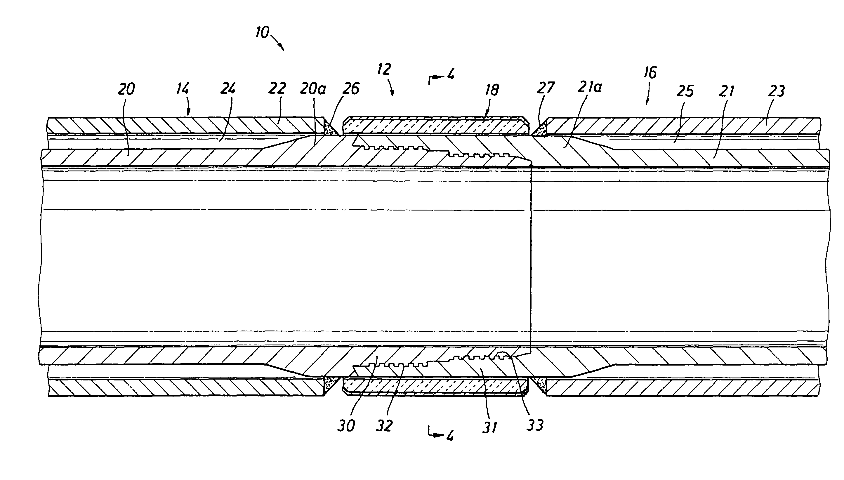
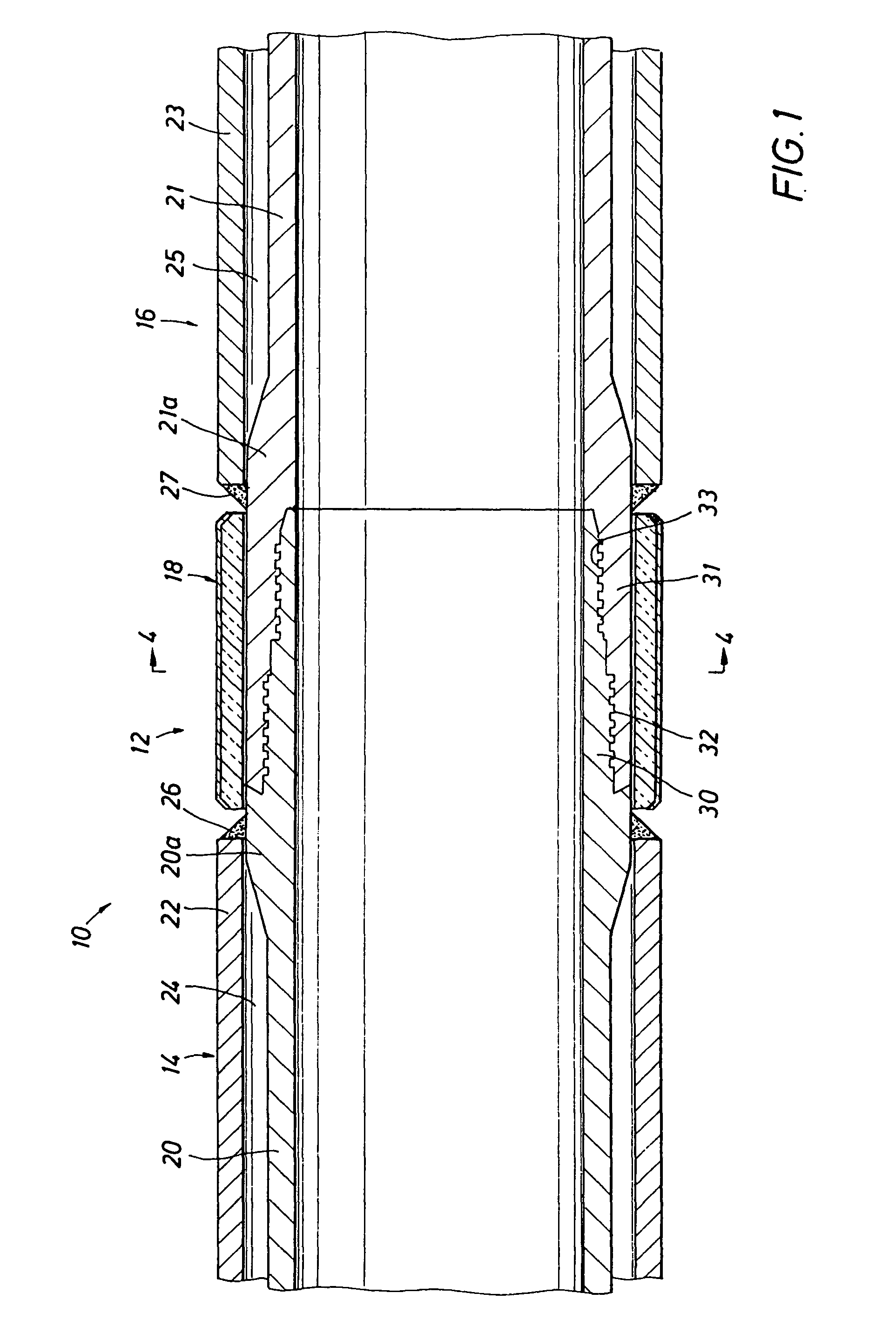
[0027]FIG. 1 shows an embodiment of an insulated tubular assembly 10, having a connection 12 between two insulated tubing segments 14, 16. An insulating sleeve 18 surrounds the connection 12. Each tubing segment 14, 16 has a double-walled insulated construction, which includes an inner tube 20, 21, an outer tube 22, 23 concentrically disposed about the inner tube 20, 21 and an annulus 24, 25 between the inner tube 20, 21 and the outer tube 22, 23. Each end of each tubing segment 14, 16 has an annular bridge 26, 27, which connects the inner tube 20, 21 to the outer tube 22, 23. The annular bridge 26, 27 may be a fillet weld joining an upset portion 20a, 21a, formed on tubes 20, 21 respectively, to outer tubes 22, 23, to seal the annulus from atmosphere. The annulus 24, 25 may thereby sustain a vacuum and / or contain an insulating material, to insulate each tubing segment 14, 16.
[0028]The inner tube 20, 21 of tubing segments 14, 16 each have an extension 30, 31 extending outwardly from...
PUM
 Abstract
Description
Claims
Application Information