
Aircraft turbopropeller

Active Publication Date: 2016-05-05
SN DETUDE & DE CONSTR DE MOTEURS DAVIATION S N E C M A
View PDF0 Cites 0 Cited by
  • Summary
  • Abstract
  • Description
  • Claims
  • Application Information

AI Technical Summary

Benefits of technology

The invention is about a new design for a turboprop engine that reduces interactions between the turbulences generated by the blade tips of the propellers and the downstream propeller, while also increasing the high-speed yield and reducing noise pollution. The design includes a curved blade shape on the downstream propeller and an inverted sweepback, which helps to achieve better performance in the transonic range. By reducing the interactions, the invention achieves a higher level of high-speed yield while minimizing the noise generated during operation.

Problems solved by technology

However, a major disadvantage of this type of turboprop engine is the noise that it generates, said noise being caused in particular by the interaction of the wake or the vortex generated by the radially outer ends of the blades of the upstream propeller with the blades of the downstream propeller.
However, this solution, which is referred to as “clipping”, is not satisfactory from an aerodynamic point of view, because the loading of the rotor increases (quadratically), which penalises the yield.
Moreover, in order to distribute the excess loading, it is necessary to increase the number of blades of the downstream propeller, or the number of chords of the blades thereof, which is disadvantageous in terms of mass or bulk.
However, this solution would not be satisfactory because it would significantly increase the energy conveyed by the tip vortex.

Method used


Image

  • Aircraft turbopropeller
  • Aircraft turbopropeller

Examples


Embodiment Construction

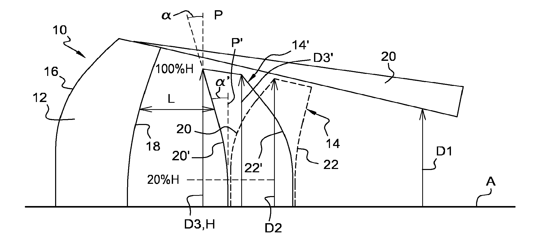
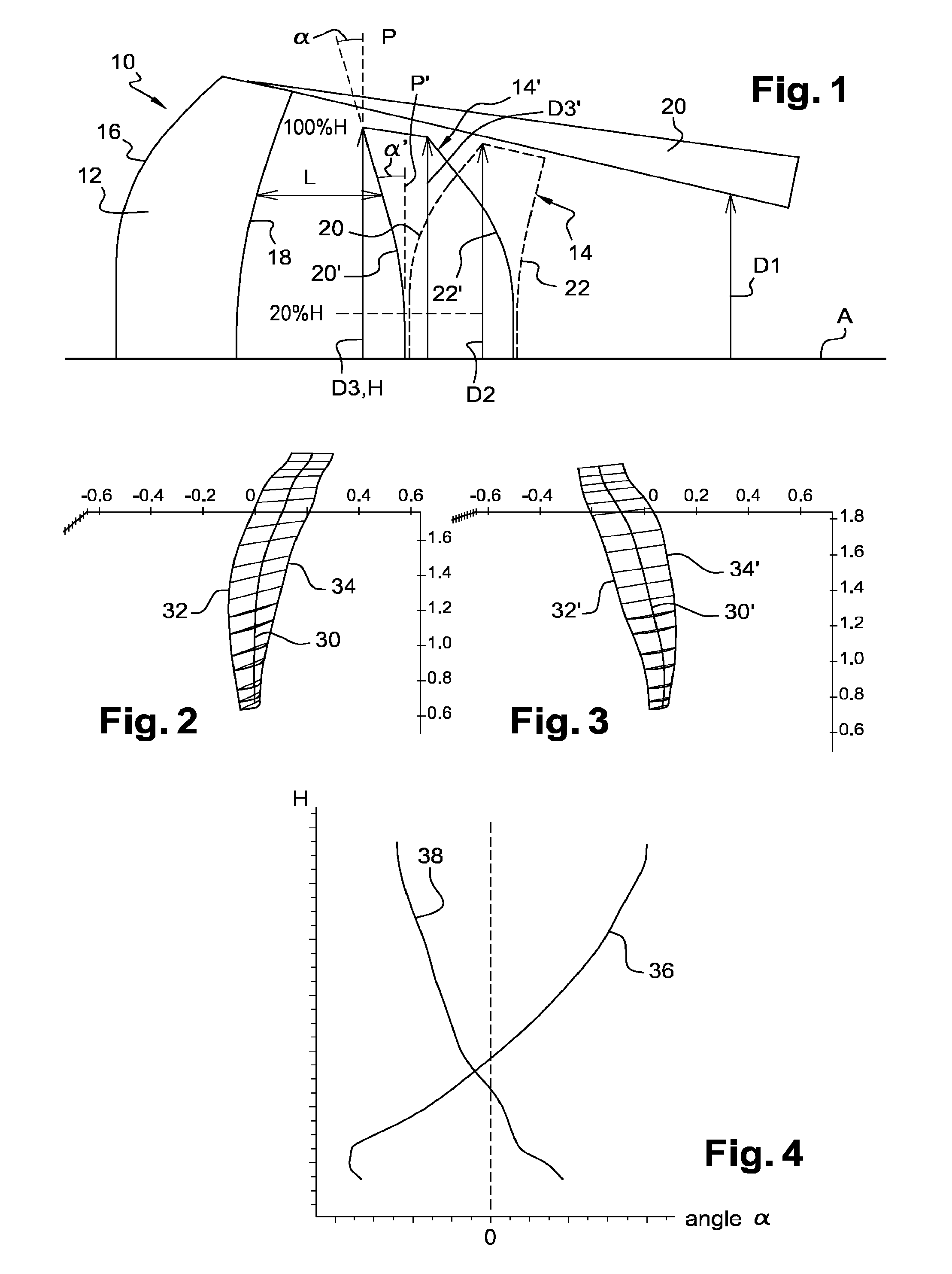
[0021]FIG. 1 shows, in a very schematic manner, a turboprop engine 10 of the open-rotor or unducted-fan type, comprising two coaxial unducted and contra-rotating propellers, which are upstream 12 and downstream 14 respectively.

[0022]The upstream propeller 10 comprises an annular array of blades which each have a rear sweepback, i.e. they are cambered towards the rear or downstream of the turboprop engine (upstream and downstream referring to the direction of flow of the gases in the turboprop engine, which is directed from left to right in the drawing).

[0023]Each blade of the upstream propeller 12 typically comprises one edge 16 leading and one edge 18 trailing the air, the edges 16, 18 extending in this case from upstream to downstream radially towards the outside, with respect to the longitudinal axis A of the turboprop engine.

[0024]The radially outer ends of the blades of the upstream propeller 12 generate a wake 20 which has a substantially rectilinear trajectory along the axis ...


PUM


Abstract

An aircraft turbopropeller includes two coaxial contra-rotating unducted propellers, upstream and downstream respectively, each propeller including an annular row of blades. The blades of the downstream propeller have a reverse sweep in relation to that of the blades of the upstream propeller. The leading edges of the blades of the downstream propeller extend radially outwards from downstream to upstream, at least over a radially outer portion of the blades.

Description

TECHNICAL FIELD[0001]The present invention relates to an aircraft turboprop engine comprising two coaxial unducted propellers, which are upstream and downstream respectively. Said turboprop engine is of the open-rotor or unducted-fan type.PRIOR ART[0002]A turboprop engine of this type comprises two propellers each comprising an annular array of substantially radial blades. The propellers are generally contra-rotating and set into rotation by a power turbine of the turboprop engine.[0003]This type of turboprop engine is particularly advantageous in terms of performance. However, a major disadvantage of this type of turboprop engine is the noise that it generates, said noise being caused in particular by the interaction of the wake or the vortex generated by the radially outer ends of the blades of the upstream propeller with the blades of the downstream propeller.[0004]A solution to this problem has already been proposed which consists in reducing the outer diameter of the downstream...

Claims


Application Information

Patent Timeline
IPC IPC(8): B64D27/10
CPCB64D27/10F01D1/26F01D5/141F02K3/072F02C3/067F05D2220/36F05D2240/303F05D2240/304F05D2240/307F05D2260/96F04D29/324B64C11/18B64C11/48B64D2027/005Y02T50/60
Inventor VLASTUIN, JONATHAN
Owner SN DETUDE & DE CONSTR DE MOTEURS DAVIATION S N E C M A
Learn More