Hand machine tool with clamping device

a technology of clamping device and hand machine tool, which is applied in the direction of manufacturing tools, flexible wheel, grinding machine components, etc., can solve the problems of time-consuming and complicated adapting the clamping stroke, and achieve the effect of high clamping force transmission

Inactive Publication Date: 2007-04-24
ROBERT BOSCH GMBH
View PDF14 Cites 46 Cited by
  • Summary
  • Abstract
  • Description
  • Claims
  • Application Information

AI Technical Summary

Benefits of technology

[0007]Because one flange defines different clamping planes, the clamping means to fit the commercially available disklike tools of different thickness can always be associated with them without calibration effort. This assures that both tools with a maximum thickness and those wit

Problems solved by technology

Adapting the clamping stroke is

Method used


Image

  • Hand machine tool with clamping device
  • Hand machine tool with clamping device
  • Hand machine tool with clamping device

Examples


Embodiment Construction

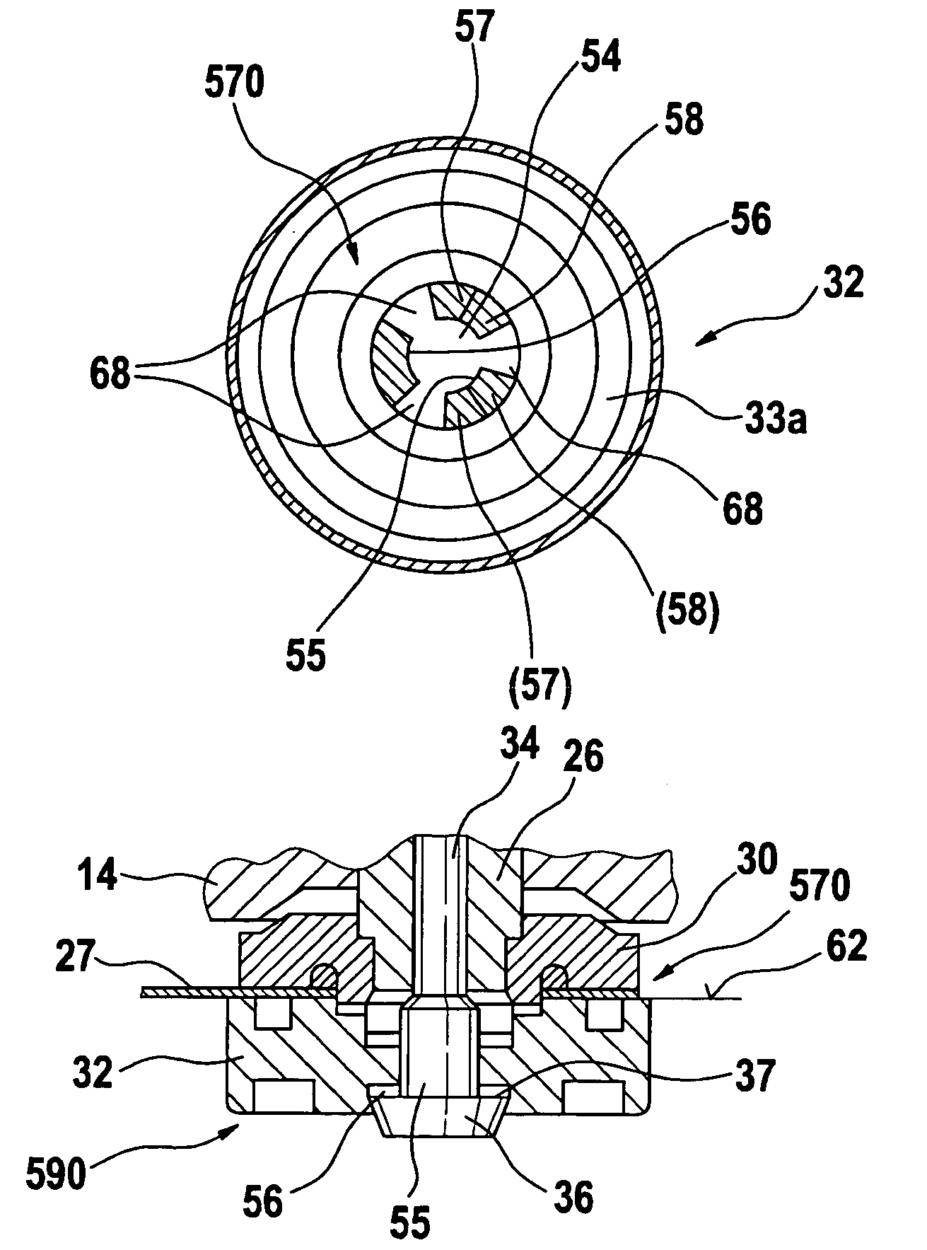
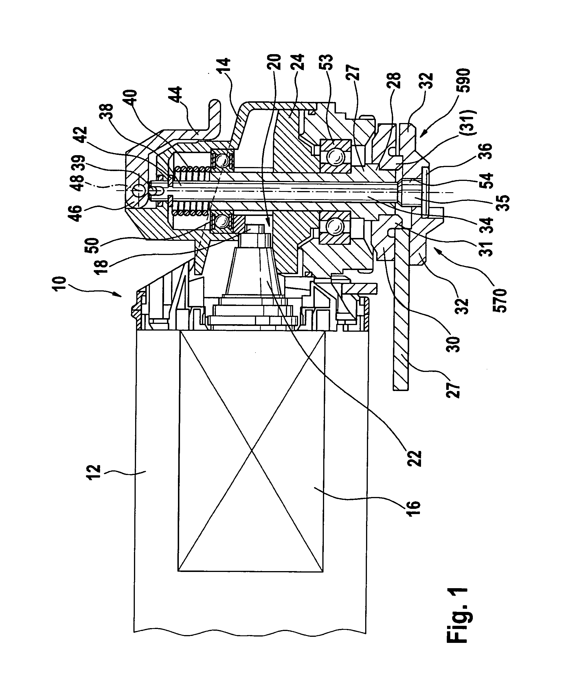
[0022]FIG. 1 shows a hand power tool 10, designed as a right-angle grinder, in longitudinal section. The hand power tool 10 comprises an elongated motor housing 12, to which a gearbox 14 bent downward at an angle is flanged. The motor housing 12 supports a motor 16, whose motor shaft 18 protrudes into the gearbox 14. The end of the motor shaft 18 supports a motor pinion 22, designed as a conical gear wheel. The motor pinion 22, together with a ring gear 24, forms an angular gear 20. In a manner fixed against relative rotation, the ring gear 24 embraces a power takeoff shaft 26, which in turn, on its end, carries a disklike tool in the form of a grinding wheel 27 in a manner fixed against relative rotation. The grinding wheel 27 is guided by a central recess, not identified by reference numeral, over the free end of the power takeoff shaft 26 and secured replaceably to it in clampable fashion. It is braced in centered fashion on the machine on the centering collar 31 of a support fla...


PUM


Abstract

A hand power tool has a disk-shaped tool, and a clamping device for clamping the tool, the clamping device including at least one flange and a clamping unit for clamping the tool to the at least one flange and passing through the tool, the clamping unit and the at least one flange being configured on a key-end-keyhole principle, so that after passing axially through one another and subsequently being rotated counter to one another, the clamping unit and the at least one flange axially fix one another at least in one axial direction.

Description

CROSS-REFERENCE[0001]The invention described and claimed hereinbelow is also described in PCT / EP 2004 / 052759, filed on Nov. 2, 2004 and DE 103 61 810.4, filed on Dec. 30, 2003. This German Patent Application, whose subject matter is incorporated here by reference, provides the basis foe a claim of priority of invention under 35 U.S.C. 119 (a)–(d).BACKGROUND OF THE INVENTION [0002]The present invention is related to a hand power tool.[0003]From European Patent Disclosure EP 152 564, a hand power tool is known whose disklike tool can be detachably secured to a work spindle for rotational slaving by means of flanges that can be locked in screwable or bayonetlike fashion.[0004]This hand power tool has a fast-action clamping means, with a tension spindle which passes through the work spindle and pulls the outer of the flanges against the disklike tool. The clamping stroke of the tension spindle must be adapted to disklike tools of different thickness, so that an adequate clamping force f...

Claims


Application Information

Patent Timeline
IPC IPC(8): B24B23/00B24B23/02B24B45/00B24D13/20
CPCB24B23/028B24B45/006B24D13/20
Inventor HESSE, JUERGENVON SPECHT, EIKE U.
Owner ROBERT BOSCH GMBH
Why Eureka
Try Eureka