Apparatus and method for analyzing a liquid in a capillary tube of a hematology instrument

a technology of capillary tubes and liquids, applied in the field of apparatus and methods for analyzing blood samples, can solve the problems of inability to determine the peak velocity of the fluid at the center of the tube, the inability to utilize optical density measurement to isolate the behavior of any one cross sectional position within the tube, and the inability to differentiate the fluid

Inactive Publication Date: 2007-04-24
COULTER INTERNATIONAL CORPORATION
View PDF23 Cites 76 Cited by
  • Summary
  • Abstract
  • Description
  • Claims
  • Application Information

AI Technical Summary

Benefits of technology

[0023]Preferably, the waveform pulse is an ultrasound pulse at a preselected frequency. In addition, preferably the sensor, or sensors, are piezo crystal transducers, the capillary tube defines a straight path of travel adjacent the sensor to ensure a laminar blood sample flow, and the ultrasound pulse is emitted in a direction substantially perpendicular to the path of travel and along a diameter of the capillary tube. Further, the device according to the present invention can be utilized to determine one or more of the fluid-type of the fluid flowing within the capillary tube, the viscosity of a blood sample flowing within the capillary tube, and the erythrocyte sedimentation rate (ESR) and zeta sedimentation rate (ZSR) of a blood sample after the flow of the blood sample within the capillary tube is abruptly halted.

Problems solved by technology

Although the aforementioned apparatus, methods, systems and techniques may function satisfactorily for their intended purposes, the use of optical density measurements has some disadvantages and significant limitations.
An optical density measurement cannot be utilized to isolate the behavior of any one cross sectional position within a tube.
For example, the optical density measurement cannot determine the peak velocity at the center of the tube nor can it differentiate the fluid velocity at the center of the tube relative to the fluid velocity at the edges of the tube.
In addition, optical density sensors are only useful when used in combination with tubing have a small inner diameter that permits a sufficient amount of light to pass through the tubing and sample.
Of course, use of small inner diameter tubing limits the fluid handling flow rate of samples through the hematology instrument.
The presence of microbubbles within a blood sample also presents a significant challenge since the presence of microbubbles are unrecognizable by optical density sensors and greatly effects the value of the optical density measurement.
Any inadvertent movement of the tube relative to the sensors will require a time consuming recalibration of the sensors.
Such inadvertent movement often occurs during the course of troubleshooting the blood-processing instrument for non-sensor related reasons.
A problem with generating blood smears is that hematology parametric data of blood samples lose value over time.
Similarly, the measurement of ESR and ZSR typically require a significant initial dead time which has a significant effect on the time required for analysis.
Such analysis, therefore, cannot readily be accomplished in succession with other analyses that can be performed much quicker, such as, for instance blood cell counts.
The ESR measurement method and apparatus according to U.S. Pat. No. 5,827,746 issued to Duic also has disadvantages due to its reliance on optical density measurements.
Lipids cause problems related to carryover and baseline drift of the optical density measurement.
The build-up causes an increase in optical attenuation of the tube and therefore, affects the optical density measurement.
Thus, there is an unknown progressive error build-up that distorts the optical density and ESR measurements of all samples processed sequentially through the apparatus.
Another limitation of the above stated method is that it requires an additional time-consuming process step of preheating the blood sample to a precise elevated temperature before the test can be started.

Method used


Image

  • Apparatus and method for analyzing a liquid in a capillary tube of a hematology instrument
  • Apparatus and method for analyzing a liquid in a capillary tube of a hematology instrument
  • Apparatus and method for analyzing a liquid in a capillary tube of a hematology instrument

Examples


Embodiment Construction

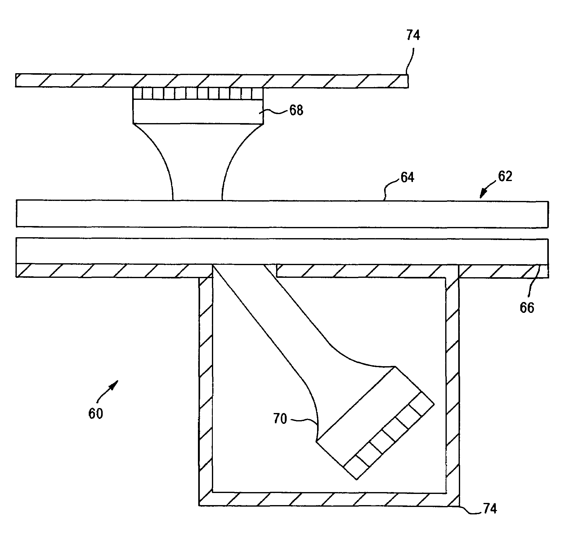
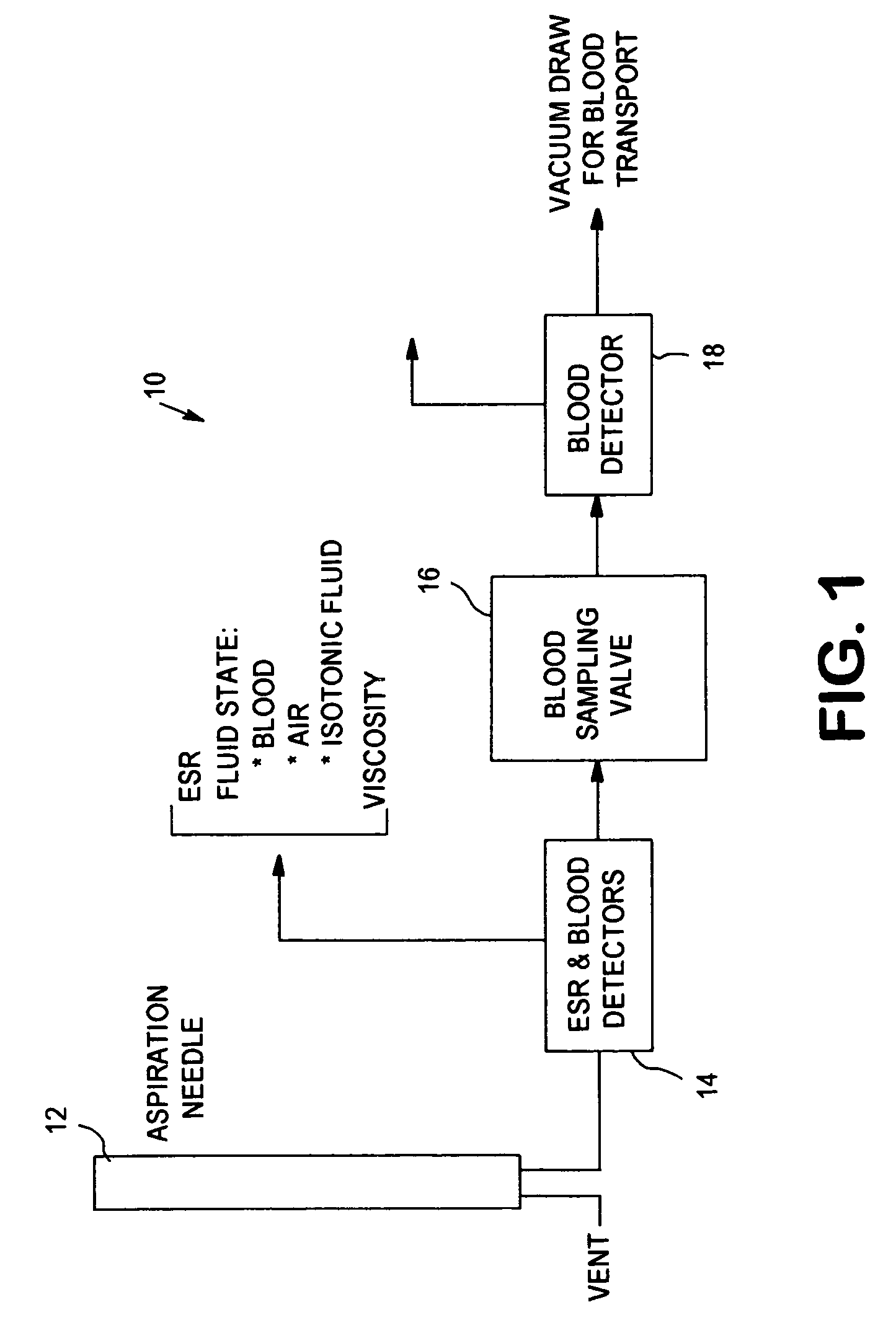
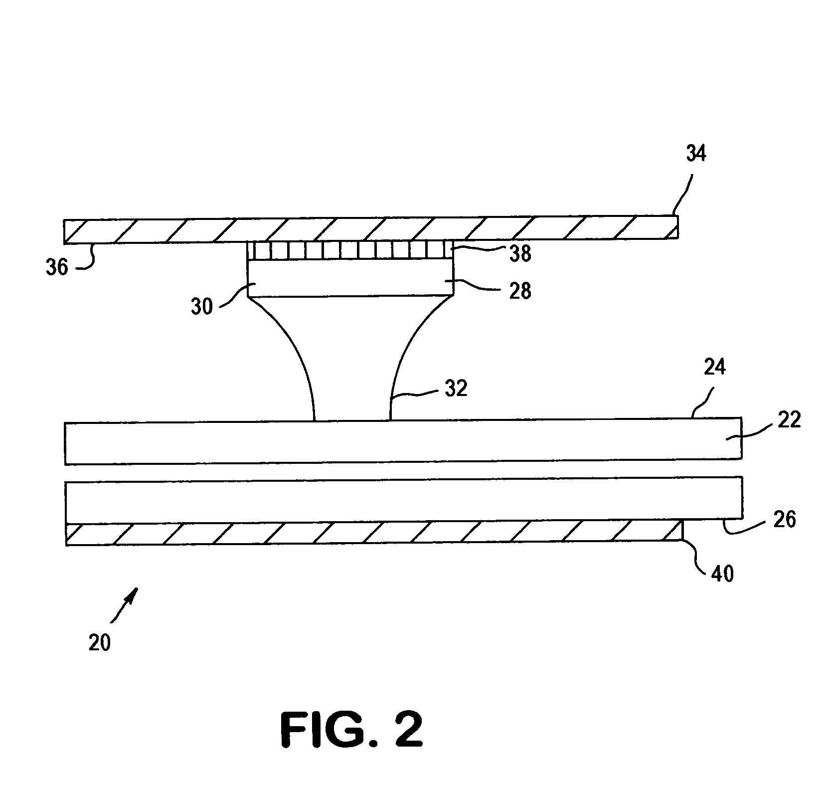
[0039]The present invention relates to an apparatus and method for analyzing a blood sample in vitro. The apparatus can be configured, for instance, as a freestanding measurement device, or a sensor, detector, or device for use in a multi functional hematology instrument, or a sensor, detector or device for use in connection with an automated blood smear slide generator. The sensor, detector or device according to the present is utilized to analyze blood samples and is capable of determining one or more of the density / fluid-type of a fluid sample, the viscosity of a blood sample, and / or the erythrocyte sedimentation rate (ESR) and zeta sedimentation rate (ZSR) of a blood sample.

[0040]The present invention also relates to a multifunctional hematology instrument having one or more of the above referenced sensors, detectors or devices, and to an automated blood smear slide generator used in connection with one or more of the above referenced sensors, detectors or devices. In addition, ...


PUM

PropertyMeasurementUnit
wall thicknessaaaaaaaaaa
propagation velocityaaaaaaaaaa
sizesaaaaaaaaaa

Abstract

An apparatus and method for determining the density and fluid-type of a fluid flowing in a capillary tube, the velocity and viscosity of a blood sample flowing in a capillary tube, the erythrocyte sedimentation rate (ESR) of a blood sample after flow has been brought to an abrupt stop in a capillary tube, and/or the zeta sedimentation rate (ZSR) of a blood sample after flow has been brought to an abrupt stop in a capillary tube. These measurements are accomplished by directing a waveform pulse, such as an ultrasound pulse, at a pre-determined frequency transversely across the capillary tube and sample fluid, and by determining the flight of time of the pulse through the capillary tube and sample fluid and/or the Doppler shift of the echo signals reflecting off cells moving forwardly or transversely within a flowing, or stationary, blood sample.

Description

FIELD OF THE INVENTION[0001]The present invention relates to an apparatus and method for analyzing a blood sample in vitro, and more particularly, the present invention relates to a hematology instrument, sensor, or the like, and method which are utilized to analyze blood samples and / or are associated with the generation of blood smear slides and which are capable of determining one or more of the density / fluid-type of the sample, the viscosity of the sample, and the erythrocyte sedimentation rate (ESR) and zeta sedimentation rate (ZSR) of the sample.BACKGROUND OF THE INVENTION[0002]An apparatus for analyzing blood samples in vitro typically requires fluids to be passed through a capillary tube in a predefined sequence, such as, air, isotonic fluids (ie., salt water), blood, isotonic fluids and then air. The apparatus typically includes one or more fluid-type detectors for determining the presence, or lack thereof, of blood within the capillary tube at various locations along the le...

Claims


Application Information

Patent Timeline
Patent Type & Authority Patents(United States)
IPC IPC(8): A61B5/00A61B8/00G01N11/04G01N15/05G01N29/024G01N33/49
CPCG01N11/04G01N15/05G01N29/024G01N33/491G01N2291/02466G01N2291/02818G01N2291/02836
Inventor HUSHER, FREDERICK K.
Owner COULTER INTERNATIONAL CORPORATION
Why Eureka
Try Eureka